Single hand rope installation mechanism and installation method

An installation mechanism and a single root technology, applied in packaging, transportation and packaging, container manufacturing machinery, etc., can solve the problems of easy damage to the bag body, inconvenient operation, hand-carrying knots and poor length consistency, and achieve a good degree of automation. Improved convenience and good consistency

Active Publication Date: 2016-12-21
杭州汇八科技有限公司
View PDF8 Cites 0 Cited by
  • Summary
  • Abstract
  • Description
  • Claims
  • Application Information

AI Technical Summary

Problems solved by technology

[0006] The invention provides a single handle rope installation mechanism and a single handle rope installation method which can pass the two ends of a single handle rope into the inside of the bag body and complete the knotting action, so as to solve the problem of The operation method of manually installing a single handle rope on the bag body has the problems of easy damage to the bag body, inconvenient operation, poor knot and length consistency of the handle rope

Method used


Image

  • Single hand rope installation mechanism and installation method
  • Single hand rope installation mechanism and installation method
  • Single hand rope installation mechanism and installation method

Examples


Embodiment 1

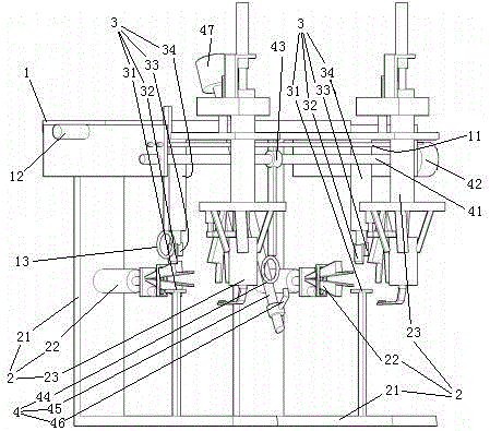
[0040] Embodiment one, see figure 1 , a single handle rope installation mechanism, including a frame 1. The frame 1 is provided with two rope-threading and knotting mechanisms 2, two cutting knives 3 and a hand rope fixed-length feeding mechanism 4.

[0041] Two threading and knotting mechanisms 2 are distributed on the frame 1 along the left and right directions. Two threading and knotting mechanisms 2 are located between two cutting knives 3 . The threading and knotting mechanism 2 includes a mounting base 21 and a rope-threading manipulator 22 and a knotting structure 23 arranged on the mounting base 21 .

[0042] The cutting knife 3 includes an anvil 31 disposed on the mounting base 21 , a blade 32 and a pressing block 33 located above the anvil 31 . The blade 32 and the pressing block 33 are installed on the mounting base 21 through the cutting cylinder 34 .

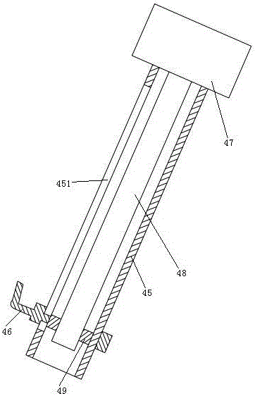
[0043] The hand rope fixed-length feeding mechanism 4 includes a rope pick ring 44, a guide rod 45 and a rope...

Embodiment 2

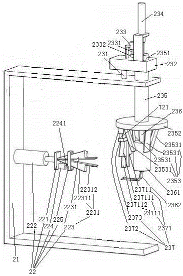
[0069] Embodiment two, the difference with embodiment one is: see Figure 6 , the rope-threading clips 2231 are hinged together through the hinge shaft 2232 . The outer surface of the rope clip closing control section 22311 is a tapered surface. An expansion spring 2233 is arranged between the pair of rope-threading clips 2231 . The free end face 223121 of chuck is spherical. The pair of stringing clips 2231 are kept apart by expanding the spring 2233 . The structural form of the rope-winding clip that constitutes the rope-winding manipulator is the same as the structural form of the rope-threading clip.

[0070] see Figure 7 The rope withdrawal structure 2353 includes a rope withdrawal ring 23532 sleeved on the rope winding section 2361 and a connecting rod 23533 for suspending the rope withdrawal ring 23532 on the turntable 2352 . The lifting rod 236 is provided with an adsorption channel 2363 extending along the vertical direction. The inlet 23631 of the adsorption c...


PUM


Abstract

The present invention relates to a device and a method for connecting a handle cord to a bag body. The device includes a frame, a hand rope fixed-length feeding mechanism, two rope-threading knotting mechanisms and two cutters. The rope-threading knotting mechanism includes a mounting seat, a rope-threading manipulator, a first actuator and The lifting base driven by the components, the lifting base is provided with a third actuator, a second actuator, a vertical rotating shaft driven by the third actuator and a lifting rod driven by the second actuator, the lower end of the rotating shaft is connected to the turntable and is located on the turntable. The rope-winding manipulator at the bottom, the lifting rod passes through the rotating shaft and extends out of the turntable, the cutting knife includes a cutting board, blade and pressing block, and the hand rope fixed-length feeding mechanism includes a pickable rope ring, a guide rod and a rope that can move along the guide rod The hook, the guide rod and the two threading manipulators are located in the same plane. The invention solves the problems of easy damage to the bag body, inconvenient operation, and poor consistency of the knot and length of the hand rope existing in the installation process of the hand rope.

Description

technical field [0001] The invention relates to a device and a method for connecting a hand rope to a bag body, in particular to an installation mechanism and an installation method for installing a single hand rope on a bag body, and belongs to the field of hand paper bag processing. Background technique [0002] There are two kinds of structures for the user to carry the existing portable paper bag, one is the hand hole directly opened on the bag body, and the other is to be connected to the bag body to carry the hand. [0003] In Chinese Patent No. 2004200254298, the date of authorization announcement is March 2, 2005, and the patent literature titled "handy paper bag" discloses a kind of handy paper bag made of bag rope (handle) and bag body. The connection mode between the bag body and the hand rope in this patent document is: a rope hole is opened on the bag body, the two ends of the hand rope pass through the rope hole from the outside to the inside, and a The rope b...

Claims


Application Information

Patent Timeline
Patent Type & Authority Patents(China)
IPC IPC(8): B31B1/86B31B50/86
Inventor 李璟
Owner 杭州汇八科技有限公司
Why Eureka
Try Eureka