
High-flame-retardant fireproof cooling distribution box

A power distribution box, high flame retardant technology, applied in the substation/power distribution device shell, electrical components, fire rescue and other directions, can solve the problem of component combustion loss, avoid damage, novel structure, improve flame retardant and flame retardant effect of ability

Active Publication Date: 2014-02-05
STATE GRID CORP OF CHINA +3
View PDF4 Cites 14 Cited by
  • Summary
  • Abstract
  • Description
  • Claims
  • Application Information

AI Technical Summary

Problems solved by technology

[0002] Electricity is one of the important energy sources in our country. Since the reform and opening up, with the rapid development of the national economy and the improvement of people's living standards, social electricity consumption has greatly increased, and the consumption of various electrical equipment and household appliances has increased sharply. Distribution boxes are The main function of the power control equipment in the home or the whole city is to centrally install switches, meters, lighting and electrical equipment. The distribution box generally has a control panel, and the box is connected together. Due to the internal temperature of the distribution box If it is too high, it will cause spontaneous combustion, and the current distribution boxes generally have the function of heat dissipation, but in the past, fans are used to dissipate heat, but electrical fire accidents are still increasing, and due to external fires, the entire The burning of components inside the distribution box is a huge loss. At present, there is a fireproof layer outside the distribution box, but it still cannot avoid the danger of burning the components inside the distribution box.

Method used


Image

  • High-flame-retardant fireproof cooling distribution box

Examples


Embodiment Construction

[0014] In order to deepen the understanding of the present invention, the present invention will be described in further detail below in conjunction with the accompanying drawings and embodiments, which are only used to explain the present invention and do not limit the protection scope of the present invention.

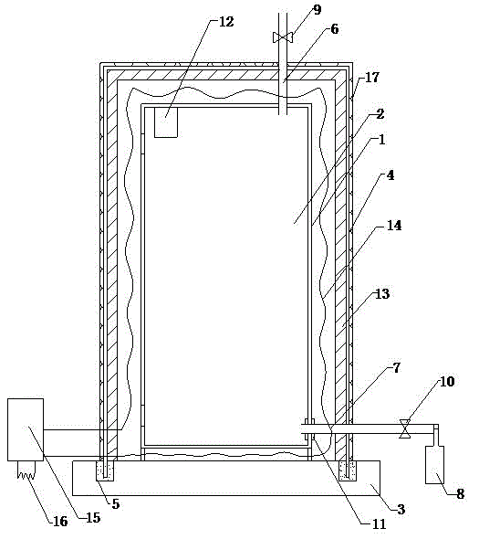
[0015] Such as figure 1 As shown, the present invention is a high flame-retardant, fire-proof and heat-dissipating distribution box, which includes an inner box body 1 and an inner box door 2 of the distribution box. When the inner box door 2 and the inner box body 1 are closed, a Rubber seal, the rubber sealing effect is good, to prevent the carbon dioxide gas in the inner box 1 from flowing out, the lower end of the inner box 1 is provided with a base 3, and the outer cover of the inner box 1 is provided with a place to insert the base 3 The housing 4 is provided with a groove 5 on the base 3 and the insertion of the housing 4, the groove and the insertion of the...


PUM


Abstract

The invention discloses a high-flame-retardant fireproof cooling distribution box which comprises an inner box body and an inner box door. The lower end of the inner box body is provided with a base, the outer side of the inner box body is covered by an outer shell inserted in the base, an oxygen discharge hose penetrates through the outer shell and is inserted in the upper end of the inner box body, a carbon dioxide intake hose penetrates through the outer shell and is inserted in one side of the lower end of the inner box body, and the outer end of the carbon dioxide intake hose is connected with a carbon dioxide gas cylinder; the oxygen discharge hose and the carbon dioxide intake hose are provided with a first magnetic valve and a second magnetic valve respectively; the top end in the inner box body is provided with a carbon dioxide detector; the carbon dioxide detector, the first magnetic valve and the second magnetic valve are all connected through the same controller. The high-flame-retardant fireproof cooling distribution box is novel in structure, the flame retardant ability and the flame resistant ability of the distribution box are enhanced, so that devices in the distribution box can be effectively protected, the damage to the devices in the distribution box due to outside fire is avoided, losses are reduced, and meanwhile maintenance cost is reduced.

Description

technical field [0001] The invention belongs to the technical field of electric power systems, and in particular relates to a distribution box, in particular to a distribution box with flame-retardant and fire-resistant components capable of protecting the internal components of the distribution box. Background technique [0002] Electricity is one of the important energy sources in our country. Since the reform and opening up, with the rapid development of the national economy and the improvement of people's living standards, social electricity consumption has greatly increased, and the consumption of various electrical equipment and household appliances has increased sharply. Distribution boxes are The main function of the power control equipment in the home or the whole city is to centrally install switches, meters, lighting and electrical equipment. The distribution box generally has a control panel, and the box is connected together. Due to the internal temperature of th...

Claims


Application Information

Patent Timeline
IPC IPC(8): H02B1/28H02B1/46H02B1/56A62C3/16
Inventor 孔健顾峰孙宏柏梁海霞
Owner STATE GRID CORP OF CHINA
Learn More