A bionic vapor chamber liquid-absorbing core

A technology of soaking plate and liquid absorbing core, which is used in indirect heat exchangers, lighting and heating equipment, etc., can solve the problems of reduced strength of soaking plate, unfavorable heat dissipation efficiency, and reduced evaporation area, etc. The effect of increasing the heat dissipation area and high heat dissipation efficiency

Active Publication Date: 2015-10-28
SOUTH CHINA UNIV OF TECH
View PDF4 Cites 2 Cited by
  • Summary
  • Abstract
  • Description
  • Claims
  • Application Information

AI Technical Summary

Problems solved by technology

At the same time, the thickness of the vapor chamber is small in the height direction, and with the development of electronic technology, the vapor chamber is required to be thinner and thinner, so the wall of the vapor chamber will become thinner to increase the volume of the chamber of the vapor chamber , but this will reduce the strength of the vapor chamber, which will cause the vapor chamber to deform or collapse after vacuuming
Therefore, in order to increase the strength, support columns are added to the vapor chamber, but the increase of support columns will greatly reduce the evaporation area, and at the same time, it will cause changes in the flow field in the chamber of the chamber, which is not conducive to the improvement of heat dissipation efficiency

Method used


Image

  • A bionic vapor chamber liquid-absorbing core
  • A bionic vapor chamber liquid-absorbing core
  • A bionic vapor chamber liquid-absorbing core

Examples


Embodiment 1

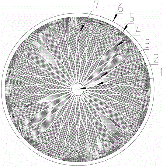
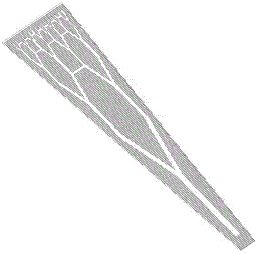
[0045] see figure 1 , figure 2 , image 3 As shown, a bionic vapor chamber liquid-absorbing core includes a central condensation area 1 for containing liquid working fluid, a main transport channel 2, a support column 3, a connecting channel 4, an annular flange 5, a condensation base plate 6, and a fine channel 7. The condensing substrate 6 is provided with a boss area, and the central condensing area 1 is arranged in the middle of the boss area of ​​the condensing substrate 6 in a circular groove shape, and the main transportation channel 2 is connected to the central condensing area 1 and Taking the central condensation area 1 as a common starting point, the leaf veins of binary tree structure are evenly distributed on the condensation substrate 6 toward the edge of the condensation substrate 6, and the main transport channels 2 are connected horizontally by the connecting channel 4, so that all the main transport channels The transportation channel 2 forms a network cha...

Embodiment 2

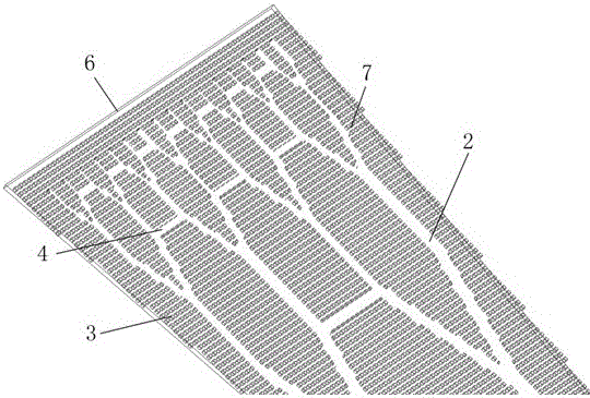
[0050] see picture figure 1 , figure 2 , image 3 , Figure 4 As shown, the difference between this embodiment and Embodiment 1 is that the boss area is formed by uniformly sintering the silk screen on the condensation substrate 6 using vacuum sintering technology, and the bifurcation angle of the main transport channel 2 is 45°. The length ratio of the latter branch to the adjacent previous branch is 0.7, and the width ratio is 0.5.

[0051] Further, the liquid working medium is any one of purified water, methanol, ethanol, and acetone.

Embodiment 3

[0053] see figure 1 , figure 2 , image 3 , Figure 6 As shown, a bionic vapor chamber liquid-absorbing core includes a central condensation area 1 for containing liquid working fluid, a main transport channel 2, a support column 3, a connecting channel 4, an annular flange 5, a condensation base plate 6, and a fine channel 7. The condensing substrate 6 is provided with a boss area, and the central condensing area 1 is arranged in the middle of the boss area of ​​the condensing substrate 6 in a circular groove shape, and the main transportation channel 2 is connected to the central condensing area 1 and Taking the central condensation area 1 as a common starting point, the leaf veins of binary tree structure are evenly distributed on the condensation substrate 6 toward the edge of the condensation substrate 6, and the main transport channels 2 are connected horizontally by the connecting channel 4, so that all the main transport channels The transportation channel 2 forms ...


PUM


Abstract

The invention discloses a bionic vapor chamber liquid-absorbing core. The structure of the liquid-absorbing core is based on the efficient transport structure of plant leaves, and is designed according to the transport principle of plant leaves from point to surface and the principle of the shortest path of transport. A novel vapor chamber imitating the transport structure of plant blades. The soaking plate can be integrated with the liquid-absorbing core, so that the working fluid can quickly enter the fractal channel under the action of capillary pressure, and the working fluid transported through the fractal channel can quickly enter the polygonal microstructure surrounded by the fractal channel. And quickly reach the entire condensation surface of the soaking plate, quickly condense into a liquid state, and then return to the evaporation end under the action of capillary pressure. After completing a cycle, it is ready for the next evaporation. At the same time, the polygonal micro-channel structure imitating the leaf vein structure promotes the liquid working fluid to quickly flow to the periphery of the condensation end along the network channel of the liquid-absorbing core, which speeds up the circulation of the working fluid transmission circuit and improves the heat transfer efficiency. The overall size is small and suitable for in sophisticated electronic equipment.

Description

technical field [0001] The invention relates to a bionic soaking plate liquid-absorbing core structure, which effectively overcomes the defects of the existing soaking plate liquid-absorbing core technology such as large flow resistance, slow transmission, local microchannel blockage, low temperature uniformity, and low strength. , can efficiently solve the problem of local heat dissipation of electronic devices. Background technique [0002] With the development of electronic technology, circuit integration technology continues to promote the increasingly sophisticated electronic products. At the same time, highly integrated electronic devices have caused a sharp increase in heat flux, and heat dissipation has become an insurmountable bottleneck in the development of electronic technology. As an efficient heat transfer device, the vapor chamber has been widely used in the heat dissipation of electronic equipment. As the core structure of the vapor chamber, the liquid-abso...

Claims


Application Information

Patent Timeline
Patent Type & Authority Patents(China)
IPC IPC(8): F28D15/02
CPCH01L23/473
Inventor 刘旺玉彭毅陈伟田玉福黄家乐
Owner SOUTH CHINA UNIV OF TECH
Why Eureka
Try Eureka