
Conductive polymer dispersions for solid electrolytic capacitors

A conductive polymer layer and capacitor technology, applied in the field of improved capacitors, improved cathodes, and the manufacture of inherently conductive polymer dispersions, can solve problems such as high leakage, exposure, and low operating voltage

Active Publication Date: 2016-10-12
KEMET ELECTRONICS CORP
View PDF16 Cites 0 Cited by
  • Summary
  • Abstract
  • Description
  • Claims
  • Application Information

AI Technical Summary

Problems solved by technology

Regardless of the type of conductive polymer used, the main disadvantages of conductive polymer capacitors are: 2 Conductive polymer capacitors have a relatively low operating voltage compared to their counterparts
[0017] Another problem with solid electrolytic capacitors containing conductive polymers is high leakage at high temperatures and after being subjected to surface mount conditions
However, these solutions do not address the balance between moisture resistance / low moisture absorption and water retention required for solid electrolytic capacitors with improved reliability
The above solutions also do not solve the problems associated with SMT reflow exposure

Method used

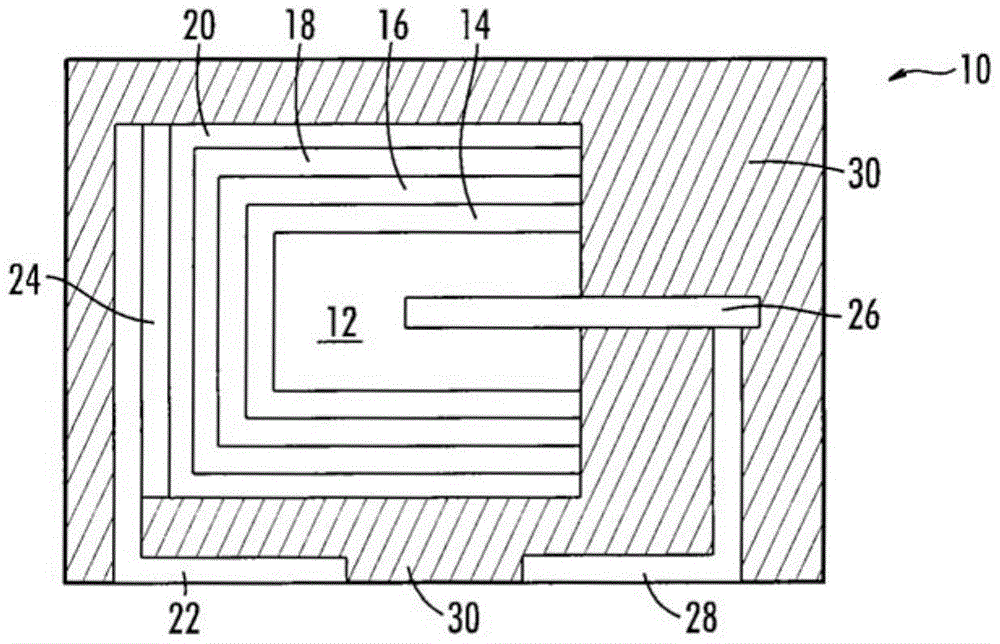

Image

  • Conductive polymer dispersions for solid electrolytic capacitors
  • Conductive polymer dispersions for solid electrolytic capacitors
  • Conductive polymer dispersions for solid electrolytic capacitors

Examples


Embodiment 1

[0090] A part was prepared in the same manner as in Comparative Example 1 except that a hydrophilic polymer polyethylene oxide (marked as HL) was used to prepare a conductive polymer dispersion. A conventional graphite coating is applied followed by a silver layer. The parts were assembled and the ESR measured before and after surface mounting. The relationship between the moisture content and the leakage current was measured, and it is described in Table 2.

Embodiment 2

[0092] A part was prepared in the same manner as in Comparative Example 1 except that an oligomer having hydroxyl and carboxyl groups (marked as HP) available for crosslinking was used to prepare a conductive polymer dispersion. A conventional graphite coating is applied followed by a silver layer. The parts were assembled and the ESR measured before and after surface mounting. The relationship between the moisture content and the leakage current was measured, and it is described in Table 2.

[0093] Table 2

[0094]

Embodiment 3

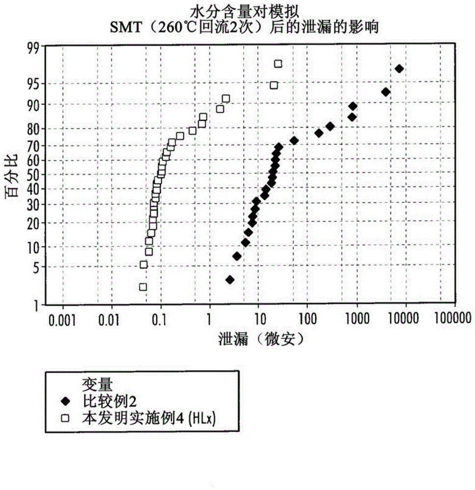
[0096]A part was prepared in the same manner as in Comparative Example 1, except that a conductive polymer dispersion was prepared using a polymer mixture containing polyethylene oxide, polyvinyl alcohol, and hydroxyethyl cellulose (marked for HLx). A conventional graphite coating is applied followed by a silver layer. The parts were assembled and the ESR measured before and after surface mounting. The moisture content measured by the Karl Fischer method was 24% by weight, while that of Comparative Example 2 was 18% by weight. After a post-simulation SMT (two cycles) at 260 °C, the effect of moisture content on leakage is in image 3 displayed in .


PUM

PropertyMeasurementUnit
glass transition temperatureaaaaaaaaaa
critical surface tensionaaaaaaaaaa
water absorptionaaaaaaaaaa

Abstract

A capacitor has an anode and a dielectric over the anode. There is a first conductive polymer layer on the dielectric, wherein the first conductive polymer layer includes a polyanion and a first binder. On the first conductive polymer layer there is a second conductive polymer layer, wherein the second conductive polymer layer comprises a polyanion and a second binder, wherein the first binder is more adhesive than the second binder The agent is more hydrophilic.

Description

[0001] Cross References to Related Applications [0002] This application claims priority to US Pending Provisional Application No. 61 / 489571, filed May 24, 2011, the contents of which are incorporated herein by reference. Background technique [0003] The present invention relates to an improved method of forming a solid electrolytic capacitor and an improved capacitor formed thereby. More specifically, the present invention relates to an improved cathode comprising a highly conductive polymer dispersion coating with enhanced reliability. The present invention also discloses a method of making the intrinsically conductive polymer dispersion. The present invention relates to an improved method of forming a solid electrolytic capacitor and an improved capacitor formed thereby. More specifically, the present invention relates to a capacitor with improved leakage stability. [0004] The construction and fabrication of solid electrolytic capacitors is well documented in the lit...

Claims


Application Information

Patent Timeline
Patent Type & Authority Patents(China)
IPC IPC(8): H01G9/012H01G9/048
CPCH01G9/0032H01G9/0036H01G9/028H01G9/042H01G9/048H01G9/15
Inventor 安东尼·P·查科
Owner KEMET ELECTRONICS CORP
Learn More