
Bearing type RV speed reducer

A reducer and bearing technology, which is applied in the field of bearing-type RV reducer, can solve the problems of tapered roller bearings easy to wear, reduce transmission accuracy, and reduce service life, so as to increase service life, improve transmission reliability and precision, and reduce The effect of manufacturing costs

Inactive Publication Date: 2014-01-22
SHANDONG SHKE MACHINERY MFG
View PDF6 Cites 19 Cited by
  • Summary
  • Abstract
  • Description
  • Claims
  • Application Information

AI Technical Summary

Problems solved by technology

[0006] The purpose of the embodiment of the present invention is to provide a bearing-type RV reducer to solve the problem that the robot RV reducer provided by the prior art requires three power input shafts to be supported on the planetary carrier through the bearing positions of the tapered roller bearings for power transmission. , the manufacturing cost is high, and the tapered roller bearings are easy to wear, resulting in reduced matching accuracy, poor reliability, and further problems of reduced transmission accuracy and service life

Method used


Image

  • Bearing type RV speed reducer
  • Bearing type RV speed reducer
  • Bearing type RV speed reducer

Examples


Embodiment Construction

[0025] In order to make the object, technical solution and advantages of the present invention clearer, the present invention will be further described in detail below in conjunction with the accompanying drawings and embodiments. It should be understood that the specific embodiments described here are only used to explain the present invention, not to limit the present invention.

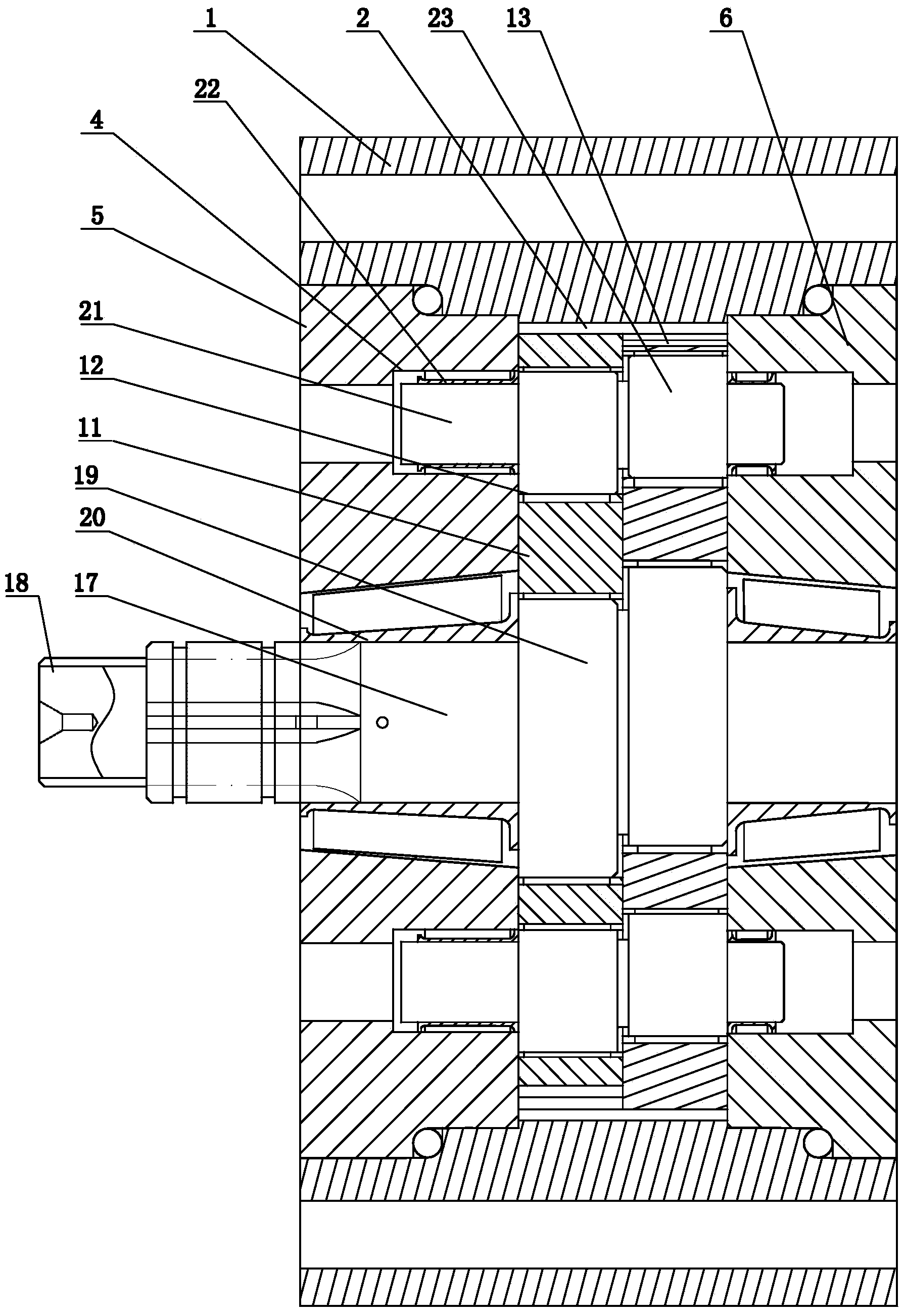
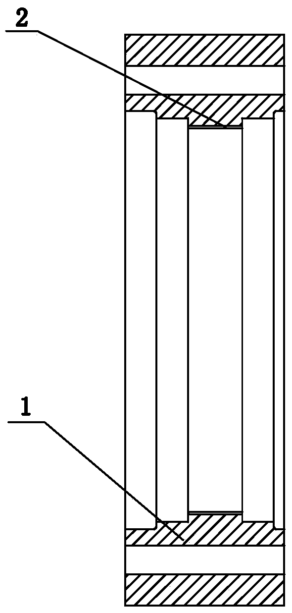
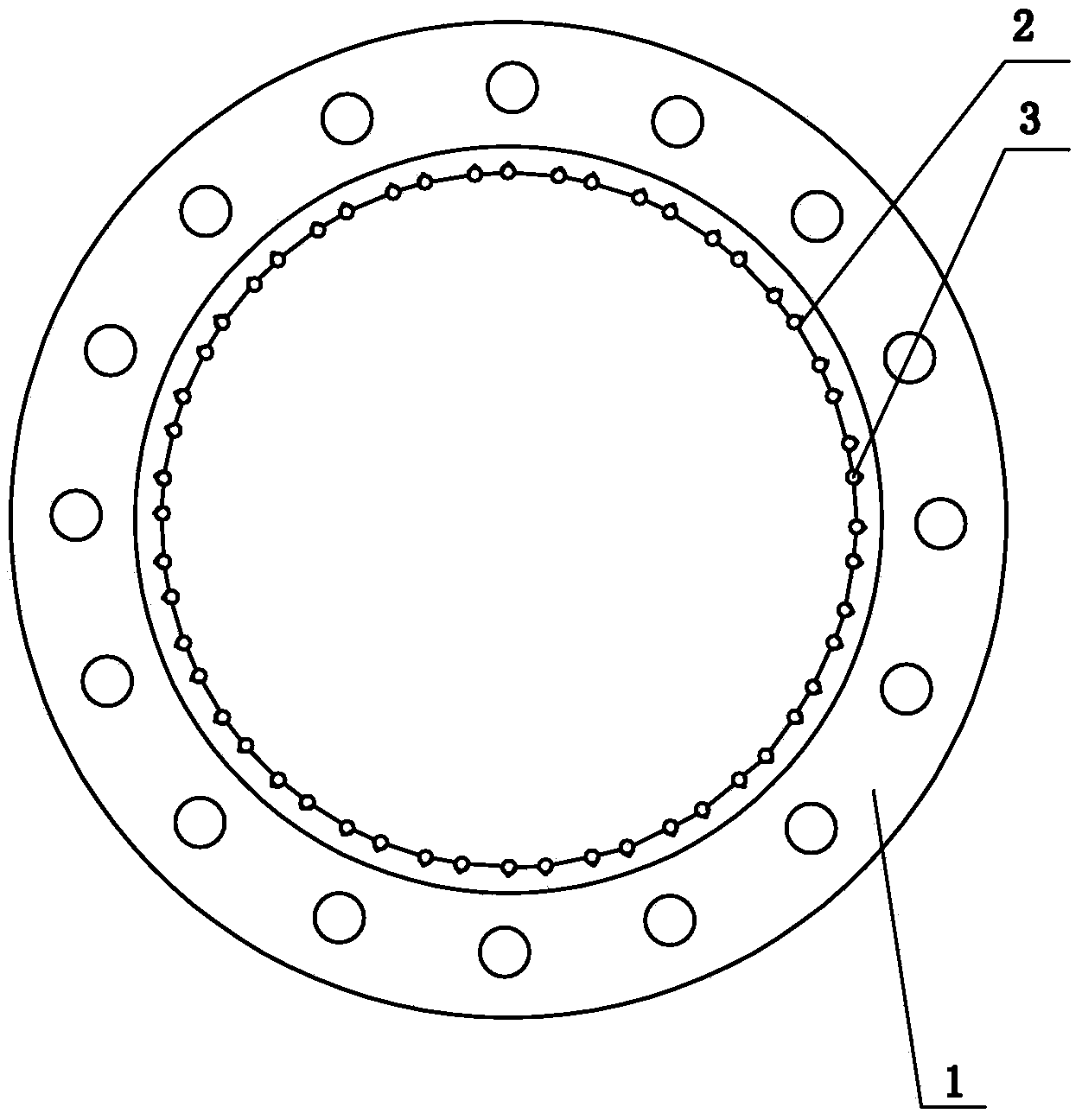
[0026] Such as figure 1 As shown, the bearing-type RV reducer includes a mounting frame 8 rotatably mounted on the pin gear housing 1. There are several densely arranged needle grooves 2 in an annular array on the inner ring of the pin gear housing 1 with the smallest inner diameter. Slot 2 is a peach-shaped slot (see figure 2 and image 3 ); the mounting bracket 8 includes a first unit 5 and a second unit 6 mounted together by locking elements (see Figure 4 ), the locking element is a bolt connector, or other connectors to realize this function, two cycloidal wheels 11 are arranged between th...


PUM


Abstract

The invention discloses a bearing type RV speed reducer, and belongs to the technical field of speed reducers. The speed reducer comprises a pin wheel housing, an installation frame is arranged in the pin wheel housing in a rotary mode, the installation frame is provided with two cycloid gears in transmission connection with the pin wheel housing through needle rollers, the installation frame is rotatably provided with a power input shaft, the power input end of the power input shaft extends out of the installation frame, the power input shaft is provided with two eccentric drive wheels which penetrate through the centers of the two cycloid gears respectively and are matched with the corresponding cycloid gears, the installation frame is rotatably provided with at least two positioning shafts which are symmetric to the rotation center of the power input shaft, and each positioning shaft is provided with two eccentric transmission wheels which penetrate through the two cycloid gears respectively and are matched with the cycloid gears. Power center input and first speed reduction are achieved. Compared with the prior art, the bearing type RV speed reducer reduces the number of power input shafts and use of sun gears and planetary gears, manufacturing cost is low, transmission is reliable, machining and installation are convenient to achieve, and service life is prolonged.

Description

technical field [0001] The invention belongs to the technical field of reducers, in particular to a bearing type RV reducer. Background technique [0002] At present, the commonly used robot RV reducer includes a pin gear housing. The pin gear housing is provided with a planet carrier formed by connecting two monomers through connecting elements. There are two cycloidal wheels between the two monomers. The body is arranged in a circular array and correspondingly provided with three bearing positions of tapered roller bearings. The three sets of corresponding bearing positions are provided with a crankshaft connected to the power device, and each crankshaft passes through two cycloidal wheels. hole on the top. The robot RV reducer adopting this structure first transmits the power device (sun gear) to the three crankshafts (planetary gears) at the same time, and the crankshaft drives the two cycloidal wheels to run, and the cycloidal gears transmit the power to the pin gear h...

Claims


Application Information

Patent Timeline
Patent Type & Authority Applications(China)
IPC IPC(8): F16H1/28F16H1/32F16H57/023
CPCF16H1/32F16H57/023F16H57/08F16H2001/323F16H2001/327F16H2057/085
Inventor 汤承龙
Owner SHANDONG SHKE MACHINERY MFG
Learn More