
Method and drilling tool for directional-blasting well drilling

A technology of directional blasting and drilling, which is applied in the field of natural gas exploitation and petroleum, which can solve the problems of increasing drilling cost, affecting oil and gas circulation, increasing oil and gas flow resistance, etc., and achieves the effects of reducing the incidence of drilling accidents, simple and convenient operation, and accelerating drilling speed

Inactive Publication Date: 2014-01-22
SOUTHWEST PETROLEUM UNIV
View PDF5 Cites 3 Cited by
  • Summary
  • Abstract
  • Description
  • Claims
  • Application Information

AI Technical Summary

Problems solved by technology

For the drilling system, not only the drilling rig needs to transmit huge torque to drive the drill bit at the bottom of the well, but also a set of expensive solid control system equipment is required. The drilling fluid used in it is not only expensive, but also pollutes the environment , which virtually increases the cost of drilling
When drilling encounters loose formations, permeable formations or formation fracture zones, etc., lost circulation accidents will occur, which may directly cause well collapse, drill sticking and even lead to loss of control of formation pressure, resulting in more serious well kick or blowout accidents ;During drilling, the drilling fluid in the well loses water, which will reduce the cementing force of the rock, and some rocks will swell and peel off after being soaked, which will lead to the stability and collapse of the well wall, causing accidents such as pipe sticking; When the drilling fluid produces solid particles and mud cakes that may block the oil and gas channels, the filtrate will expand the clay in the formation and block the pores of the formation. Increase oil and gas flow resistance, affect the flow of oil and gas, thereby reducing production value
When drilling into solid and tight rock formations, in order to maintain a high drilling speed, it is necessary to maintain a high drilling speed, which will increase the wear of the teeth of the drill bit and reduce the service life; due to the high hardness of the tight rock formation, the high pressure loaded on the drill bit will also Increases the chance of accidents such as broken teeth

Method used


Image

  • Method and drilling tool for directional-blasting well drilling
  • Method and drilling tool for directional-blasting well drilling
  • Method and drilling tool for directional-blasting well drilling

Examples


Embodiment Construction

[0017] The present invention will be further described below in conjunction with accompanying drawing:

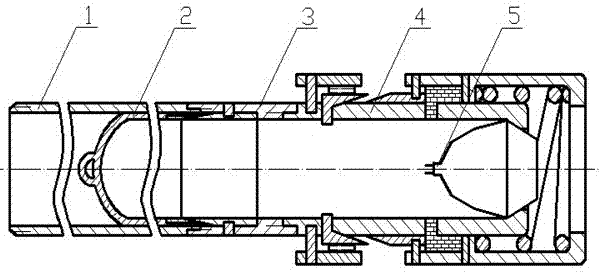
[0018] The present invention relates to a method for directional blasting drilling. The method is as follows: the rock is melted and extruded by the high-energy jet generated by the explosion of the perforating charge 5 to form a large perforation similar to that formed by explosive blasting, and the melted rock will It will be compacted and then cooled to form a layer of solid rock formation, which can achieve the purpose of well cementing; then through the mechanism, the perforating charges 5 can be exploded intermittently one by one at a suitable position in the perforation, and the hole depth will be continuously increased. Large, so as to achieve the purpose of circular directional blast drilling.

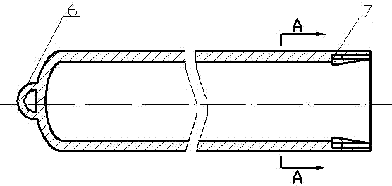
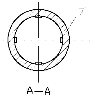
[0019] as attached figure 1 , figure 2 , image 3 , Figure 4 , Figure 5 As shown, a drilling tool for directional blasting drilling in the present invention mainly ...


PUM


Abstract

The invention relates to a method and drilling tool for directional-blasting well drilling in petroleum and natural gas well drilling. The method comprises the steps that rocks are melted and divided in an extruding mode through high-energy jet flows generated through explosion of perforating bullets, a large-aperture jet hole similar to a hole after explosive blasting is formed, perforating bullets can explode one by one at intervals in proper positions in the jet hole through a mechanism, and therefore the purpose of circulative directional blasting well drilling is achieved. The drilling tool mainly comprises a bullet bin, perforating bullets and a gun head. The bullet bin is a hollow steel pipe with one side sealed, a hanging ring is arranged at the sealed position of the bullet bin, and four bullet bin wedge slide keys are arranged at the position, not sealed, of the bullet bin. When the bullet bin is fully filled, the bullet bin wedge slide keys stretch out to prevent the perforating bullets from falling down, and when the bullet bin reaches the connector, the bullet bin wedge slide keys retreat in a sliding mode, and the perforating bullets can fall down to the automatic bullet sending position of the gun head. According to the method and drilling tool, cost is saved, the well drilling speed is improved, the accident rate of well drilling can be reduced, and operation is simple and convenient.

Description

technical field [0001] The invention relates to a directional blasting drilling method and a drilling tool for oil and natural gas drilling, belonging to the field of oil and natural gas exploitation. Background technique [0002] Modern drilling methods mostly adopt mechanical rotary drilling. This method has achieved great results after long-term development, but it also has shortcomings. For the drilling system, not only the drilling rig needs to transmit huge torque to drive the drill bit at the bottom of the well, but also a set of expensive solid control system equipment is required. The drilling fluid used in it is not only expensive, but also pollutes the environment , which virtually increases the cost of drilling. When drilling encounters loose formations, permeable formations or formation fracture zones, etc., lost circulation accidents will occur, which may directly cause well collapse, drill sticking and even lead to loss of control of formation pressure, resul...

Claims


Application Information

Patent Timeline
Patent Type & Authority Applications(China)
IPC IPC(8): E21B7/00E21B7/04
Inventor 何畏熊尉伶邱亚玲李波周晓敏胡玉茂
Owner SOUTHWEST PETROLEUM UNIV
Learn More