Dismounting type conveying device for pipelines

A conveying device and split-type technology, applied in the field of split-type conveying devices, can solve the problems affecting the use, danger, rolling, and even rolling out of steel pipes, and achieve the effects of avoiding waste, convenient transportation and reducing costs.

Active Publication Date: 2015-12-16
CHONGQING RUITUO BUILDING MATERIAL CO LTD
View PDF8 Cites 0 Cited by
  • Summary
  • Abstract
  • Description
  • Claims
  • Application Information

AI Technical Summary

Problems solved by technology

However, since the conveyor belt is horizontal and the steel pipe is cylindrical, when the steel pipe is placed on the conveyor belt, the steel pipe is prone to rolling, and even rolls out of the conveyor belt, hurting others, which is very dangerous; and because the steel pipe is hollow, the steel pipe In the process of rolling and falling, the wall of the steel pipe is easily deformed, which affects the use of the steel pipe

Method used


Image

  • Dismounting type conveying device for pipelines
  • Dismounting type conveying device for pipelines
  • Dismounting type conveying device for pipelines

Examples


Embodiment Construction

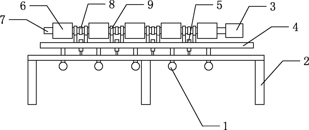
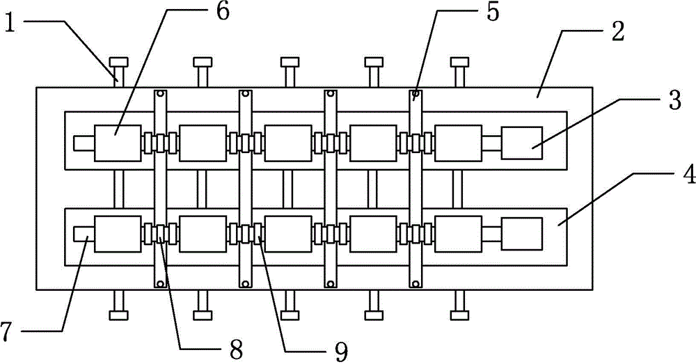
[0019] Among them: double-ended threaded rod 1, support frame 2, motor 3, support plate 4, guide block 5, large-diameter shaft 6, small-diameter shaft 7, coupling 8, and bearing seat 9.

[0020] Such as figure 1 , figure 2 As shown, the split conveying device for pipelines of the present invention includes two rotating shafts located on the same plane, the two rotating shafts are parallel to each other and inclined downward along the direction of transmission, and each rotating shaft is connected with a motor 3, and the motor 3 Starting can drive the rotating shaft to rotate.

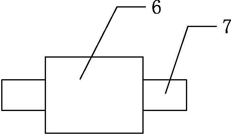
[0021] Each rotating shaft includes five sub-shafts, and each sub-axis includes a large-diameter shaft 6 and two small-diameter shafts 7, and the large-diameter shaft 6 is located between the two small-diameter shafts 7, as image 3 As shown, the outer wall of the large-diameter shaft 6 is covered with rubber, and the outer wall of the rubber is provided with a spiral texture. The spiral direction of...


PUM


Abstract

The invention discloses a dismounting type conveying device for pipelines. The dismounting type conveying device comprises two rotating shafts located on the same plane. Each rotating shaft is connected with a power device. Each rotating shaft comprises a plurality of branch shafts. Each branch shaft comprises a large-diameter shaft and two small-diameter shafts, wherein the large-diameter shaft is located between the two small-diameter shafts, rubber is arranged on the outer wall of the large-diameter shaft, and the outer wall of the rubber is provided with spiral grain. The spiral direction of the rubber grain of the same rotating shaft is consistent. Bearings are arranged at the small-diameter shafts. The bearings are sleeved with bearing blocks. The branch shafts are connected through couplers. According to the dismounting type conveying device for the pipelines, pipeline rolling can be avoided, and transporting and conveying are convenient.

Description

technical field [0001] The invention belongs to the field of conveying devices, and in particular relates to a detachable conveying device for pipelines. Background technique [0002] In municipal engineering, it is usually necessary to bury some large steel pipes underground, such as sewer pipes, etc. However, the underground environment is harsh and there are many corrosive liquids. In order to prevent the steel pipe from being corroded, people usually coat a layer of corrosion-resistant rubber on the outer wall of the steel pipe. [0003] At present, when the outer wall of a steel pipe is coated with rubber, it is usually carried out after covering one steel pipe, and then manually removes it from the coating site, and then coats the next steel pipe. However, this method is inefficient, and because the steel pipe is relatively Heavy, usually a steel pipe needs many people to move, the labor cost is high, and the labor intensity of the workers is high. [0004] In order ...

Claims


Application Information

Patent Timeline
IPC IPC(8): B65G33/06
Inventor 颜克祥
Owner CHONGQING RUITUO BUILDING MATERIAL CO LTD
Why Eureka
Try Eureka