Shock vibration snow removal device
An impact vibration and vibration device technology, applied in snow surface cleaning, construction, cleaning methods, etc., can solve the problems of equipment personal safety threats, bending and breaking of the main frame, blade damage, etc., to achieve good snow removal effect, strong and reliable power , to avoid the effect of repeated work
- Summary
- Abstract
- Description
- Claims
- Application Information
AI Technical Summary
Problems solved by technology
Method used
Image
Examples
Embodiment 1
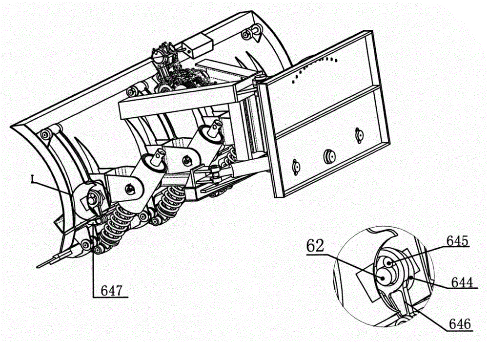
[0031] Such as image 3Shown, the present invention selects the structural representation of planar connecting rod type vibration mechanism; It comprises eccentric disk 644, crank shaft 645, crank connecting rod 646 and crank connecting rod seat 647, and eccentric disk 644 wears on the transmission shaft 62, and crank shaft 645 is fixed on the eccentric disc 644, one end of the crank connecting rod 646 is sleeved on the transmission shaft 62 and the crank shaft 645, and the other end is twisted on the crank connecting rod seat 647, and is matched with the crank connecting rod seat 647 in clearance, the crank is connected The rod seat 647 is fixed on the vibrating beam 63 . When the engine or the hydraulic pump drives the transmission shaft 62 to rotate, the transmission shaft 62 simultaneously drives the eccentric disc 644 and the crank shaft 645 on the eccentric disc to rotate eccentrically. Vibration provides a certain impact force to the blade 33 to realize vibration snow ...
Embodiment 2
[0033] Such as Figure 4 As shown, the present invention selects the structure schematic diagram of the ratchet type vibration mechanism; It comprises ratchet 648, ratchet seat 649, ratchet 650, ratchet connecting rod 651 and ratchet connecting rod seat 652, and ratchet 648 wears on the transmission shaft 62 , the pawl seat 649 is fixed on the vibrating arm 61, the pawl 650 is twisted on the pawl seat 649, and meshes with the ratchet 648, the pawl connecting rod seat 652 is fixed on the vibrating beam 63, and the pawl connecting rod 651 One end is twisted on the ratchet connecting rod seat 652, and the other end is connected with the ratchet 650. When the engine or the hydraulic pump drives the transmission shaft 62 to rotate, the transmission shaft 62 drives the ratchet 648 to rotate at the same time, and the pawl 650 drives the pawl connecting rod 651 to generate linear vibration. Under the action of this mechanism, the blade 33 vibrates synchronously.
PUM
 Abstract
Description
Claims
Application Information
 - R&D
- Intellectual Property
- Life Sciences
- Materials
- Tech Scout
- Unparalleled Data Quality
- Higher Quality Content
- 60% Fewer Hallucinations
Browse by: Latest US Patents, China's latest patents, Technical Efficacy Thesaurus, Application Domain, Technology Topic, Popular Technical Reports.
© 2025 PatSnap. All rights reserved.Legal|Privacy policy|Modern Slavery Act Transparency Statement|Sitemap|About US| Contact US: help@patsnap.com


