Speeding ship with impeller installation arched space

An impeller and space technology, applied in the direction of the hull, ship propulsion, ship parts, etc., can solve the problems of unable to seal the air, vortex intake, and affect the speed of the ship, so as to reduce the resistance of the ship, avoid air intake, and provide sufficient water supply Effect

Inactive Publication Date: 2014-01-22
CHONGQING TENGGUAN MACHINERY CO LTD
View PDF5 Cites 0 Cited by
  • Summary
  • Abstract
  • Description
  • Claims
  • Application Information

AI Technical Summary

Problems solved by technology

Because the entry of air cannot be sealed by relying on the existing technology, this problem has not been solved.
[0005] On the other hand, when the ship is running with no load or light load, the bottom of the front end of the ship is usually away from the water surface. When the ship is moving forward at high speed, the airflow is drawn into the speed-increasing tube from the space below the bottom of the front end of the ship along with the water, which is easy to appear. The problem of vortex air intake affects the further improvement of ship speed

Method used


Image

  • Speeding ship with impeller installation arched space
  • Speeding ship with impeller installation arched space
  • Speeding ship with impeller installation arched space

Examples


Embodiment Construction

[0024] The present invention will be further described below in conjunction with the accompanying drawings and examples.

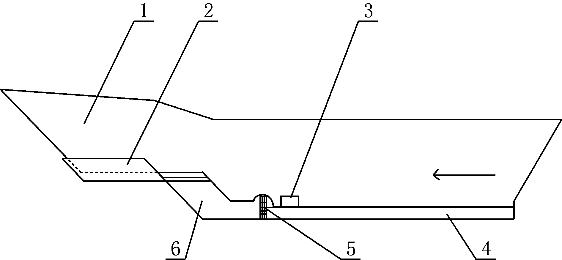
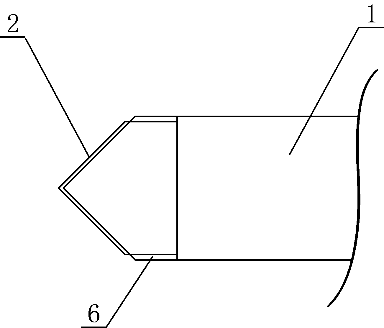
[0025] Such as figure 1 As shown, the present embodiment includes a hull 1 with a power machine 3, the front end of the hull 1 has a tip, and the bottom surface of the tip of the hull 1 is level with the full-load waterline of the ship. The bottom surface of the ship outside the tip portion is of the same height in the fore-and-aft direction; the two sides 6 are equidistant in the fore-and-aft direction.

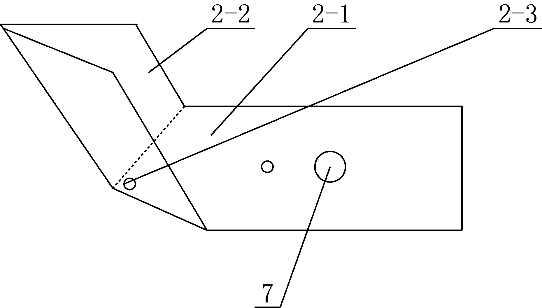
[0026] The bottom of the ship is provided with a speed-increasing tube 4 at the bottom of the hull 1, and the left and right sides of the front end of the speed-increasing tube 4 are respectively provided with a side of the ship 6, the upper end of the side of the ship 6 is connected to the hull 1, and the lower end is connected to the speed-up tube 4. The lower edge of the tube 4 is even. The water inlet of the speed-increasing pipe 4 is between the ...


PUM


Abstract

The invention provides a speeding ship with an impeller installation arched space. The front end of a ship body is provided with a ship tip, the bottom surface of the ship tip is flush with a full-load waterline of the ship, the bottom of the ship body is provided with a speed increasing pipe, the left side and the right side of the front end of the speed increasing pipe are provided with ship boards, the upper end of each ship board is connected with the ship body, and the lower end of each ship board is flush with the lower edge of the speed increasing pipe. A water inlet of the speed increasing pipe is formed between the two ship boards. One or more than two impellers are arranged in the speed increasing pipe, and speed increasing pipe sections where the impellers are arranged are arched sections. The speeding ship further comprises a floating gas sealing mechanism composed of a floating gas sealing device and the two ship boards, a bottom board of the floating gas sealing device is a gas sealing floating board, the front portion of the gas sealing floating board is triangular, the two side edges of the front portion of the gas sealing floating board are fixedly connected with two vertical board, the front ends of the two vertical boards are in butt joint with each other, and the bottom edges of the two vertical boards are in butt joint with the two side edges of the front portion of the gas sealing floating boards. The inner side faces of the two vertical boards of the floating gas sealing device are attached to two sides of the ship tip, and the rear portion of the gas sealing floating board is located between the two ship boards. Running speed of the ship is higher.

Description

[0001] [0002] This application is a divisional application. The original patent number is: 201110118713.4, the application date: April 29, 2011, and the invention name is: a fast-moving ship. technical field [0003] The invention relates to a ship capable of traveling fast. Background technique [0004] The current boats are very slow, and the concept of high horsepower and low speed has been adopted. The ensuing problem is that the speed of the ship cannot be increased simply by increasing the propeller speed. There are two reasons for this phenomenon. One is that the resistance of water is greater, and the deeper the draft, the greater the resistance; the other is air intake, because the ship is driving between water and air, and the natural flow rate of water is at a certain depth. There is a certain limit. When the speed of the propeller exceeds a certain limit, there will be no water for the propeller, and the water will be cut off. At this time, the air will be a...

Claims


Application Information

Patent Timeline
Patent Type & Authority Applications(China)
IPC IPC(8): B63B1/36B63H5/04
CPCY02T70/121Y02T70/10
Inventor 牟炳彦
Owner CHONGQING TENGGUAN MACHINERY CO LTD
Why Eureka
Try Eureka