Plug connector housing

一种插接连接器、壳体的技术,应用在插接连接器壳体领域,能够解决插接连接器壳体屏蔽作用变差等问题

Active Publication Date: 2014-01-15
HARTING ELECTRIC GMBH & CO KG
View PDF7 Cites 2 Cited by
  • Summary
  • Abstract
  • Description
  • Claims
  • Application Information

AI Technical Summary

Problems solved by technology

This increases the transfer resistance and at the same time reduces the shielding effect of such a plug connector housing

Method used


Image

  • Plug connector housing
  • Plug connector housing
  • Plug connector housing

Examples


Embodiment Construction

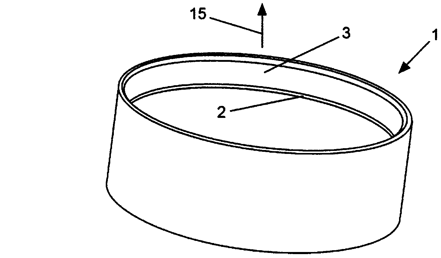
[0031] exist figure 1 A perspective view of the upper part of the housing is shown in . The housing upper part 1 shown here is essentially cylindrical. However, any other geometric shape is also conceivable, for example a rectangular parallelepiped. Possible housing shapes are disclosed in the applicant's EP957540A2 already cited above.

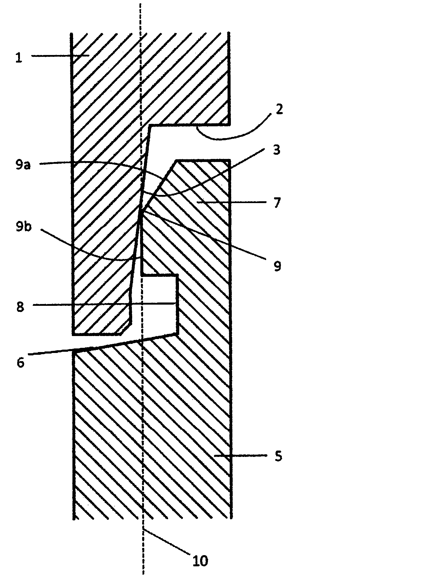
[0032] The housing upper part 1 is provided on the inside with a circumferential shoulder 2 which narrows the inner diameter of the housing upper part 1 . The contact surface 3 of the housing upper part 1 extends above the surrounding edge 2 .

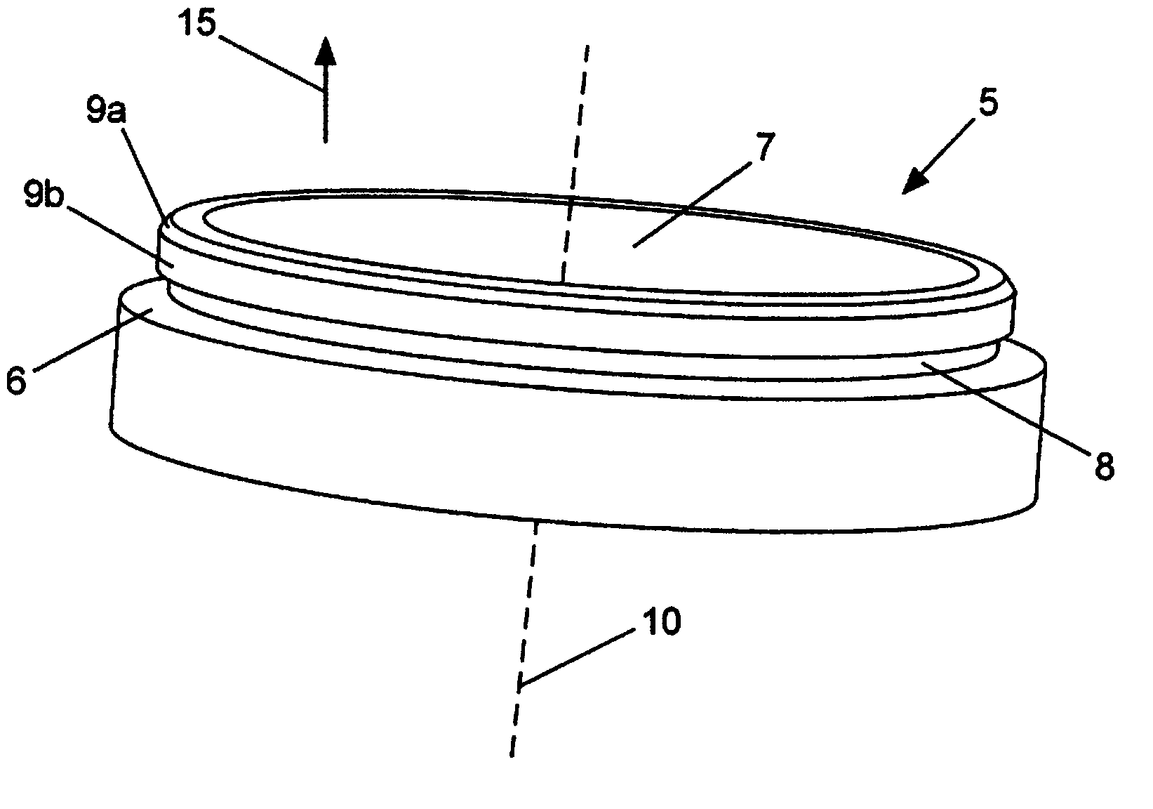
[0033] figure 2 A perspective view of the lower part of the housing is shown. The lower housing part 5 is designed in a plug-fit manner relative to the upper housing part 1 . The housing lower part 5 has an outer peripheral edge 6 on the plug-in side. An axially rising ring 7 is formed on the inside along the surrounding edge 6 .

[0034] Said ring 7 comprises a surrounding notch 8 . On the ...


PUM


Abstract

The invention relates to a plug connector housing consisting of at least one housing upper part (1) and at least one housing lower part (5) which together form a plug connector housing. The housing upper part (1) and the housing lower part (5) each have a contact surface (3, 9a, 9b), said contact surfaces (3, 9a, 9b) being at least partly in contact with each other when the housing upper part (1) and the housing lower part (5) are connected to each other. The housing upper part (1) and the housing lower part (5) are made of an electrically conductive material, said housing upper part (1) and lower part (5) having a surface coating that protects against corrosion for example, and the contact between the two contact surfaces (3, 9a, 9b) is formed along an edge (9).

Description

technical field [0001] The invention relates to a plug connector housing according to the preamble of claim 1 . [0002] Plug connector housings of this type accommodate contact elements which transmit, for example, electrical currents, light waves or also pneumatic signals. Background technique [0003] A metallic plug connector housing is used, for example, for electromagnetic shielding of the housing interior containing the contact elements already mentioned above. [0004] The quality of such shielding is usually determined by measuring the so-called transfer impedance (also called coupling resistance). The lower the transfer impedance, the higher the shielding effect of the plug connector housing. The determination of transfer impedance is a usual task for technicians in test laboratories of the electronics industry. [0005] EP957540A2 shows an electrically shielded plug connector housing. In order to electrically connect the two housing parts to one another, the s...

Claims


Application Information

Patent Timeline
Patent Type & Authority Applications(China)
IPC IPC(8): H01R4/26H01R13/6581H01R4/60H01R13/502
CPCH01R4/26H01R4/60H01R13/502H01R13/6474H01R13/6581Y10T403/70H01R4/24
Inventor T·贝内肯Y·多布里克S·达姆施G·施塔普费尔德
Owner HARTING ELECTRIC GMBH & CO KG
Why Eureka
Try Eureka