Eureka AIR delivers breakthrough ideas for toughest innovation challenges, trusted by R&D personnel around the world.

Method and device for bus signal transmission and receiving

A technology of bus signal and transmission method, which is applied in the field of error-proof bus signal transmission, receiving method and device, can solve the problems that cannot be effectively prevented, signal register errors, etc., and achieve the effect of improving correctness and preventing signal transmission errors

Inactive Publication Date: 2014-01-15
GUANGZHOU AUTOMOBILE GROUP CO LTD
View PDF4 Cites 10 Cited by
  • Summary
  • Abstract
  • Description
  • Claims
  • Application Information

AI Technical Summary

Problems solved by technology

[0004] However, this mechanism still cannot effectively prevent the signal from being interfered by EMC (Electro Magnetic Compatibility, electromagnetic compatibility) during the transmission process or the signal is caused by an error in the internal register of the control unit.

Method used


Image

  • Method and device for bus signal transmission and receiving
  • Method and device for bus signal transmission and receiving
  • Method and device for bus signal transmission and receiving

Examples


Embodiment Construction

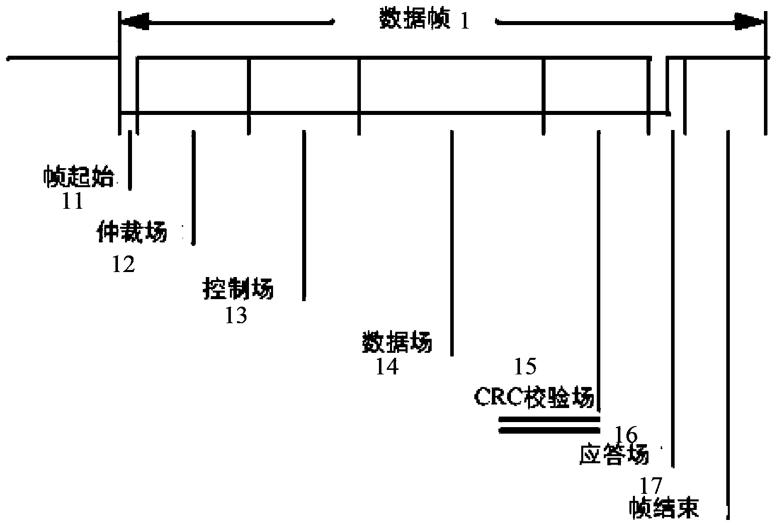
[0025] figure 1 Shows the data frame format defined by CAN2.0, data frame 1 includes the following bit fields: frame start 11, arbitration field 12, control field 13, data field 14, CRC check field 15, response field 16, frame end 17 .

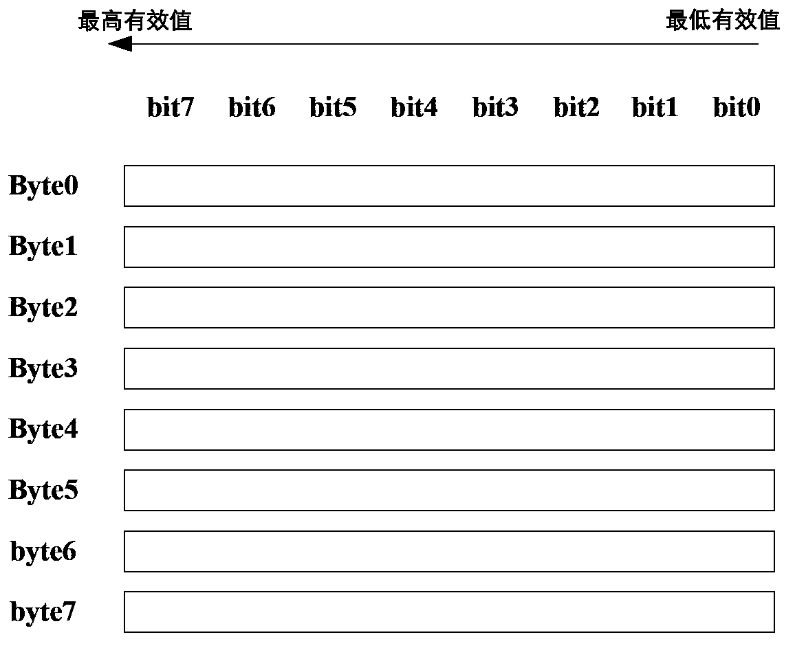
[0026] figure 2 show figure 1 In the data field structure of the CAN bus message, when the CAN bus is used for data transmission, an identifier (ID) is first assigned to the data frame 1, and then the data is filled into the data field 14 for transmission. Because the maximum number of bytes in the data field 14 is 8 bytes (byte), and one byte is 8 bits (bit), so the data that can be transmitted in one frame of data frame 1 is 8*8=64 (bit) bits data.

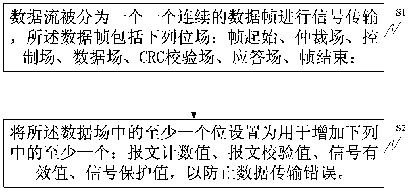
[0027] like image 3 As shown, the present invention provides a bus signal transmission method, comprising the following steps:

[0028] Step S1, the data stream is divided into successive data frames for signal transmission, and the data frame includes the following bit fields: frame sta...


PUM


Abstract

The invention provides a method and device for bus signal transmission and receiving. The bus signal transmission method includes the steps that data streams are divided into continuous data frames, signal transmission is conducted, and the data frames comprise the following potential fields, namely the start of frames, an arbitration field, a controlling field, a data flow, a CRC check field, an answering field and the end of frames; at least one potential in the data field is used for being added to at least one of a message count value, a message proof test value, a signal effective value and a signal protection value to prevent data transmission errors. The bus signal receiving method includes the steps that after a signal receiving device receives signals, an algorithm mechanism the same as the signal transmission device is adopted to calculate the message count value, the message check value, the signal effective value or the signal protection value, and then the values obtained through calculation are compared with the received corresponding values; if the values obtained through calculation are the same as the received value, the signals are in effect, and if one of the values obtained through calculation is not the same as the received value, errors occur in signal transmission.

Description

technical field [0001] The invention relates to the technical field of signal transmission and reception, in particular to an error-proof bus signal transmission and reception method and device. Background technique [0002] CAN (Controller Area Network) is a serial data communication protocol developed by the German BOSCH company in the early 1980s to solve the data exchange between numerous control and test instruments in modern automobiles. CAN2.0A / B is the version of this agreement. The format and transmission mode of CAN bus communication messages are defined in CAN2.0A / B. [0003] In the CAN2.0A / B specification, the CRC (Cyclic Redundancy Check, Cyclic Redundancy Check) check mechanism has been adopted for the transmission of messages and signals to prevent errors in the transmitted signals. The working principle of CRC code error detection: CRC code error detection is to treat the bit sequence of the processed message as a coefficient of a binary polynomial A(x), an...

Claims


Application Information

Patent Timeline
Patent Type & Authority Applications(China)
IPC IPC(8): G06F13/38
Inventor 张雁英黄少堂程艳阶钱三平智慧杨雪
Owner GUANGZHOU AUTOMOBILE GROUP CO LTD
Why Eureka
Eureka Blog
Learn More