Eureka AIR delivers breakthrough ideas for toughest innovation challenges, trusted by R&D personnel around the world.

A smt production rhythm control system and its self-locking delay loop

A technology of control system and rhythm, applied in the direction of comprehensive factory control, electrical program control, comprehensive factory control, etc., can solve the problems of easy chemical reaction with oxygen in the air, brittle contact, affecting welding effect, etc.

Active Publication Date: 2018-10-26
RF360 TECH (WUXI) CO LTD
View PDF6 Cites 0 Cited by
  • Summary
  • Abstract
  • Description
  • Claims
  • Application Information

AI Technical Summary

Problems solved by technology

[0002] In the SMT (Surface Mount Technology) surface mount industry, each substrate will go through three steps of printing, patching, and reflow. In this kind of assembly line production, we usually hope that the machine production speed of each step is The same, but most of the bottleneck steps of the products produced in the SMT industry are SMT steps
In the placement process, it takes a long time for the placement machine to mount components, but the printing process usually takes a short time. Whenever the printing is completed, the board will be requested from the front track, and the substrate will be printed continuously, waiting for the placement. In this way From the completion of the printing step to the reflow step, the substrate will accumulate at least 10 substrates, that is, it takes at least 40 minutes for the printed substrate to enter the reflow step; The chemical composition of the paste is tin. It will easily react with oxygen in the air when it is exposed to the air for a long time. In the subsequent reflow step, it will produce tin oxide at high temperature. The tin oxide has a certain solder resistance effect, so that the components and The contact point of the substrate contact is brittle, which affects the soldering effect and makes the yield rate of SMT production low

Method used


Image

  • A smt production rhythm control system and its self-locking delay loop
  • A smt production rhythm control system and its self-locking delay loop

Examples


Embodiment Construction

[0018] The present invention will be described in detail below in conjunction with the accompanying drawings.

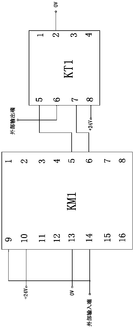
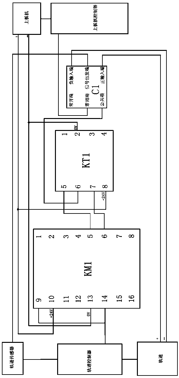
[0019] See figure 1 , a kind of self-locking time-delay circuit of the present invention, comprises relay KM1 and time relay KT1, and relay KM1 and time relay KT1 form self-locking time-delay circuit, 14 ports of relay KM1 connect external input terminal, 10 ports and 13 ports of relay KM1 The ports are respectively connected to the positive and negative poles of the 24V power supply. Port 9 of the relay KM1 is also connected to port 14 of the relay KM1. Port 6 of the relay KM1 is connected to port 7 of the time relay KT1. Port 5 of the relay KM1 is connected to port 5 of the time relay KT1. , the 2 ports and 8 ports of the time relay KT1 are respectively connected to the positive and negative poles of the 24V power supply, and the 6 ports of the time relay KT1 are connected to the external output terminal. This self-locking delay circuit can realize the delayed tran...


PUM


Abstract

The invention provides an SMT (Surface Mount Technology) production rhythm control system, which controls substrate entering time, unifies step time, and thereby reduces the exposure time of solder paste or elements, decreases solder paste oxidation, and improves an SMT production yield rate. The system comprises a loader controller, a track controller and a track sensor which are in electric control connection; the track controller induces non-existence of a substrate on an induction track through the track sensor, and then issues a signal for requiring a substrate to the loader controller. The system also comprises a relay KM1 which is in electric control connection with the track controller, and intercepts the signal for requiring a substrate issued by the track controller to trigger the relay KM1; and a time relay KT1 which is in electric control connection with the relay KM1, wherein the relay KM1 triggers the time relay KT1, and forms a self-locking time-delay loop with the time relay KT1, and the time relay KT1 delays sending the signal for requiring a substrate.

Description

technical field [0001] The invention relates to the technical field of electronic mounting, in particular to an SMT production rhythm control system and a self-locking delay circuit thereof. Background technique [0002] In the SMT (Surface Mount Technology) surface mount industry, each substrate will go through three steps of printing, patching, and reflow. In this kind of assembly line production, we usually hope that the machine production speed of each step is The same, but most of the bottleneck steps of the products produced in the SMT industry are SMT steps. In the placement process, it takes a long time for the placement machine to mount components, but the printing process usually takes a short time. Whenever the printing is completed, the board will be requested from the front track, and the substrate will be printed continuously, waiting for the placement. In this way From the completion of the printing step to the reflow step, the substrate will accumulate at le...

Claims


Application Information

Patent Timeline
Patent Type & Authority Patents(China)
IPC IPC(8): G05B19/418
CPCY02P90/02
Inventor 何烨
Owner RF360 TECH (WUXI) CO LTD
Why Eureka
Eureka Blog
Learn More