
Executing system and executing method of finite-state machine

A finite state machine and execution system technology, applied in the direction of program control devices, etc., can solve the problems of difficult maintenance and expansion of the system, complex system design, etc., and achieve the effect of easy maintenance and expansion

Inactive Publication Date: 2014-01-15
NANNING FUGUI PRECISION IND CO LTD
View PDF2 Cites 3 Cited by
  • Summary
  • Abstract
  • Description
  • Claims
  • Application Information

AI Technical Summary

Problems solved by technology

In this way, when the system includes a large number of states, each state crosses and affects each other during the transition process, resulting in more and more complex system design, making the system difficult to maintain and expand

Method used


Image

  • Executing system and executing method of finite-state machine
  • Executing system and executing method of finite-state machine
  • Executing system and executing method of finite-state machine

Examples


Embodiment Construction

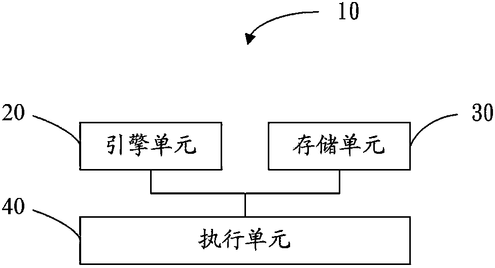
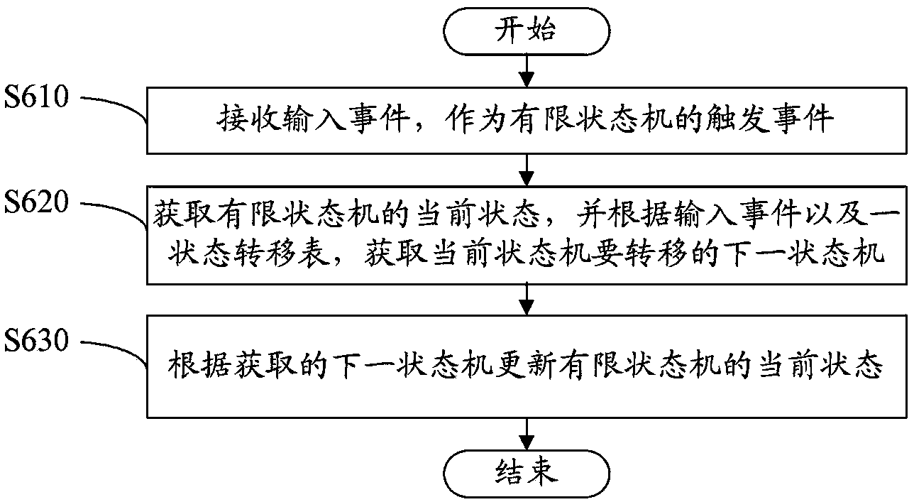
[0013] Please refer to figure 1 and figure 2 , is a block diagram of the execution system 10 of the finite state machine in an embodiment. The execution system 10 of the finite state machine includes an engine unit 20 , a storage unit 30 and an execution unit 40 .

[0014] The engine unit 20 is used for receiving an input event as a trigger event of the finite state machine.

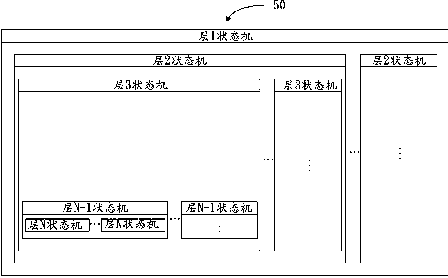
[0015] The storage unit 30 is used for storing the current state of the finite state machine and a state transition table 50 . The state transition table 50 includes an N-layer state machine, and the N-layer state machine includes a layer 1 state machine, and the layer 1 state machine includes several mutually exclusive layer 2 state machines, and each layer 2 state machine includes several mutually exclusive Layer 3 state machines, and so on, until several mutually exclusive layer N-1 state machines, each layer N-1 state machine includes several mutually exclusive layer N state machines. Among them...


PUM


Abstract

An executing system of a finite-state machine comprises an engine unit, a storage unit and an executing unit. The engine unit is used for receiving input events. The storage unit is used for storing the current state of the finite-state machine and a state transfer table. The executing unit is used for obtaining the current state of the finite-state machine from the storage unit and obtaining a next-state machine which needs to be transferred by a current-state machine and using the obtained next-state machine for updating the current state of the finite-state machine according to the input events provided by the engine unit and the state transfer state stored in the storage unit. The state transfer table comprises N layers of state machines, upper-layer state machines comprise a plurality of repellent lower-layer state machines, the lower-layer state machines are obtained through inheritance of the upper-layer state machines and the lower-layer state machines are provided with interface modules for entering the upper-layer state machines inherited by the lower-layer state machines. Each state machine in the N layers of state machines only has one living example and only processes the input event which is directly related to the living example. The invention further provides an executing method of the finite-state machine.

Description

technical field [0001] The invention relates to a finite state machine, in particular to an execution system and an execution method of the finite state machine. Background technique [0002] A finite state machine has a finite number of states, generally including states and transition relationships between states. In the system development of the finite state machine, the transition between states is realized by setting corresponding conditional statements according to the current state and the current input event. In this way, when the system includes a large number of states, each state intersects and affects each other during the transition process, which makes the system design more and more complicated, making the system difficult to maintain and expand. Contents of the invention [0003] In view of this, the present invention provides a finite state machine execution system and execution method that are easy to maintain and expand. [0004] An execution system of...

Claims


Application Information

Patent Timeline
IPC IPC(8): G06F9/44
Inventor 章国全王登勇
Owner NANNING FUGUI PRECISION IND CO LTD
Learn More