A dual-chamber electrically actuated valveless micropump

A micro-pump and actuation technology, applied in the direction of pumps, machines/engines, liquid variable capacity machines, etc., can solve the problems of small initial volume and static volume, low working efficiency, large compression ratio, etc., and achieve high flow and pressure. , simple structure, the effect of output flow and efficiency improvement

Inactive Publication Date: 2016-01-20
XINJIANG UNIVERSITY
View PDF8 Cites 0 Cited by
  • Summary
  • Abstract
  • Description
  • Claims
  • Application Information

AI Technical Summary

Problems solved by technology

The invention can reduce the pulsation of the liquid flow, and improve the problems of low working efficiency and pulsation interference of the existing valveless micropump
The invention has small initial volume and static volume, large compression ratio, good reproducibility and high reliability

Method used


Image

  • A dual-chamber electrically actuated valveless micropump
  • A dual-chamber electrically actuated valveless micropump
  • A dual-chamber electrically actuated valveless micropump

Examples


Embodiment Construction

[0027] The present invention will be further described below in conjunction with the accompanying drawings and specific embodiments.

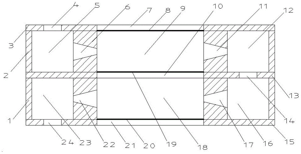
[0028] Such as figure 1As shown, the present invention includes two parts, the driving membrane and the micropump. The micropump is divided into two parts, a pump body and a pump cover, and the pump body is divided into an upper pump body 2 and a lower pump body 1 . Described pump cover is divided into upper pump cover 3, middle pump cover 13 and lower pump cover 15. The upper pump body 2 is located between the upper pump cover 3 and the middle pump cover 13, and the lower pump body 1 is located between the middle pump cover 13 and the lower pump cover 15, and the pump cover and the pump body overlap at intervals to form a micro pump. The upper pump cover 3 has a large hole 7 in the middle position, the left end of the large hole 7 is an outlet small hole 4, the middle pump cover 13 has a large hole 10, the right end of the large hole 10 is a...


PUM


Abstract

A double-cavity type electric actuator valveless micropump comprises drive films and a micropump body. The micropump body comprises a pump body and a pump cover. The pump body comprises an upper pump body (2) and a lower pump body (1); the left end and the right end of the upper pump body (2) are provided with an outlet cavity and an inlet cavity respectively; the left end and the right end of the lower pump body (1) are provided with an inlet cavity and an outlet cavity respectively; an upper pump cavity (9) is arranged between the inlet cavity and the outlet cavity of the upper pump body (2); a lower pump cavity (18) is arranged between the inlet cavity and the outlet cavity of the lower pump body (1); the upper pump cavity (9) and the lower pump cavity (18) are opposite. The pump cover is divided into an upper pump cover (3), a middle pump cover (13) and a lower pump cover (15); the upper pump body (2) is located between the upper pump cover (3) and the middle pump cover (13); the lower pump body (1) is located between the middle pump cover (13) and the lower pump cover (15); the upper pump cavity (9) is communicated with the outlet cavity and the inlet cavity through a shrinkage flow pass and a diffusion flow pass; the lower pump cavity (18) is communicated with the outlet cavity and the inlet cavity through a shrinkage flow pass and a diffusion flow pass; the inlet cavity of the upper pump body (2) and the outlet cavity of the lower pump body (1) are communicated through a middle layer small hole (14); the three drive films cover a large hole in the upper pump cover (3), a large hole in the middle pump cover (13) and a large hole in the lower pump cover (15) respectively.

Description

technical field [0001] The invention relates to a delivery device for micro-flow liquid. Background technique [0002] The micro-flow system can accurately detect and control the flow rate of microliters per minute. As the core component of the system, the micropump has become a research hotspot of domestic and foreign scholars in recent years. Because the micropump can infuse a certain amount of liquid and control the infusion speed, it is used to infuse special drugs that require accurate and stable infusion speed. Such as cardiotonic agents, vasoactive drugs, etc., and thus widely used in biopharmaceuticals. For example, diabetics used to inject a large dose of insulin at one time, which not only caused waste, but also had a short duration of drug action. Therefore, there is a great need for a continuous drip device that can control the flow rate in a small amount. In this kind of fine flow control box and detection system, the micro pump is a basic element. [0003] ...

Claims


Application Information

Patent Timeline
Patent Type & Authority Patents(China)
IPC IPC(8): F04B43/04
Inventor 陈洁木黑提
Owner XINJIANG UNIVERSITY
Why Eureka
Try Eureka