Rotary optical coder

A technology of optical encoder and encoding method, applied in the field of rotary optical encoder

Inactive Publication Date: 2007-10-31
台达绿色科技新加坡私人有限公司
View PDF7 Cites 0 Cited by
  • Summary
  • Abstract
  • Description
  • Claims
  • Application Information

AI Technical Summary

Problems solved by technology

[0006] The technical problem to be solved by the present invention is how to overcome the increase in the output of the phase commutation signal in the rotary optical encoder provided by the known technology, which results in an increase in the space used by the encoder disc, an increase in the light receiving components, and an increase in the volume of the required illumination source. And other issues

Method used


Image

  • Rotary optical coder
  • Rotary optical coder
  • Rotary optical coder

Examples


Embodiment Construction

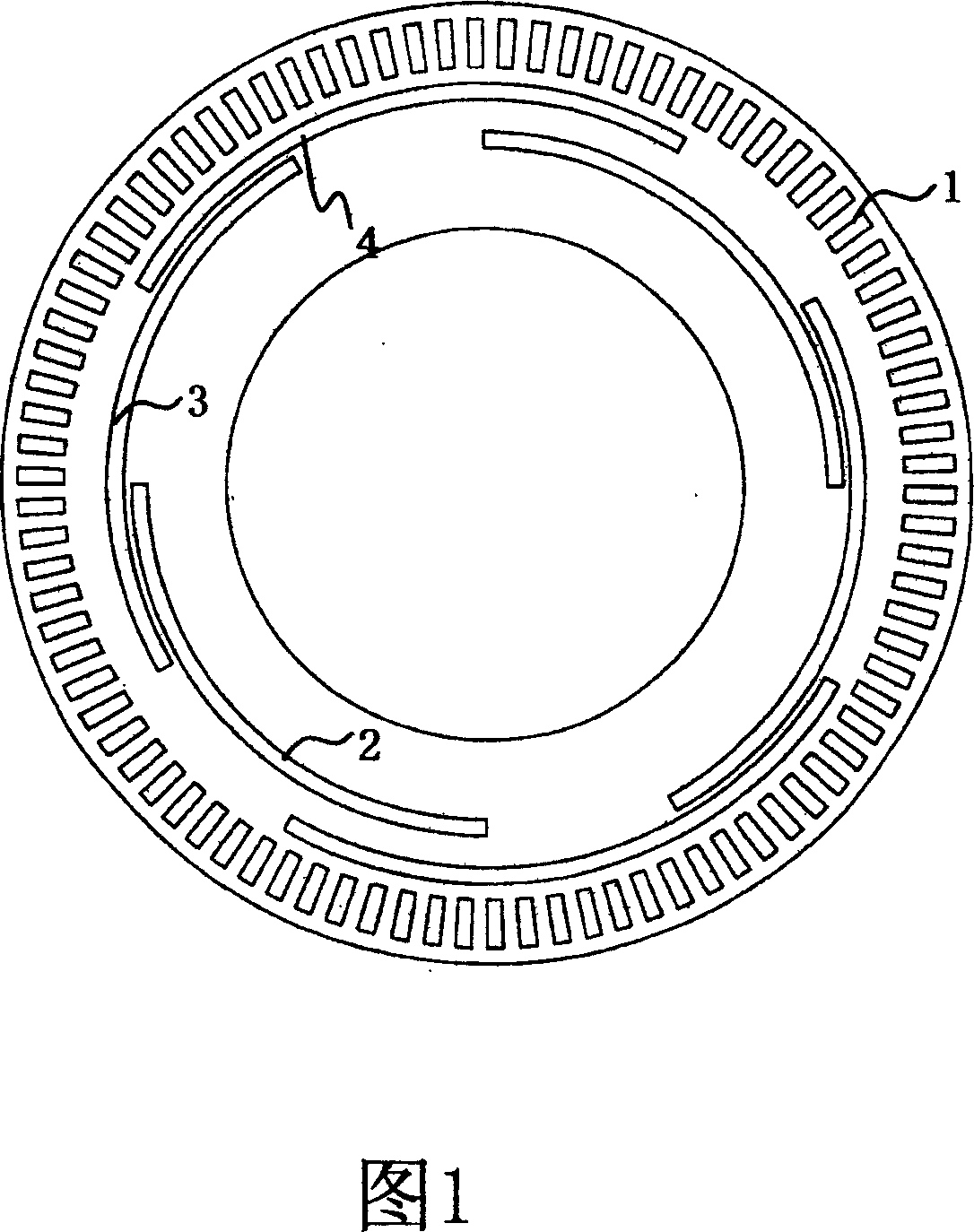
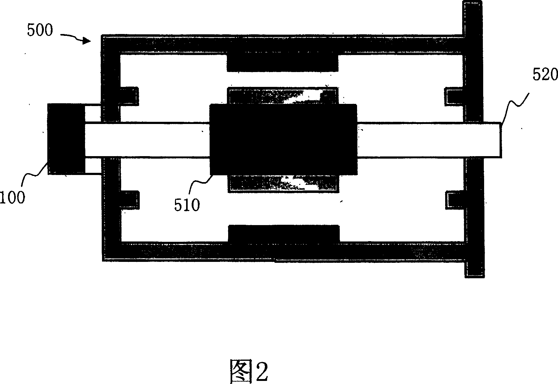
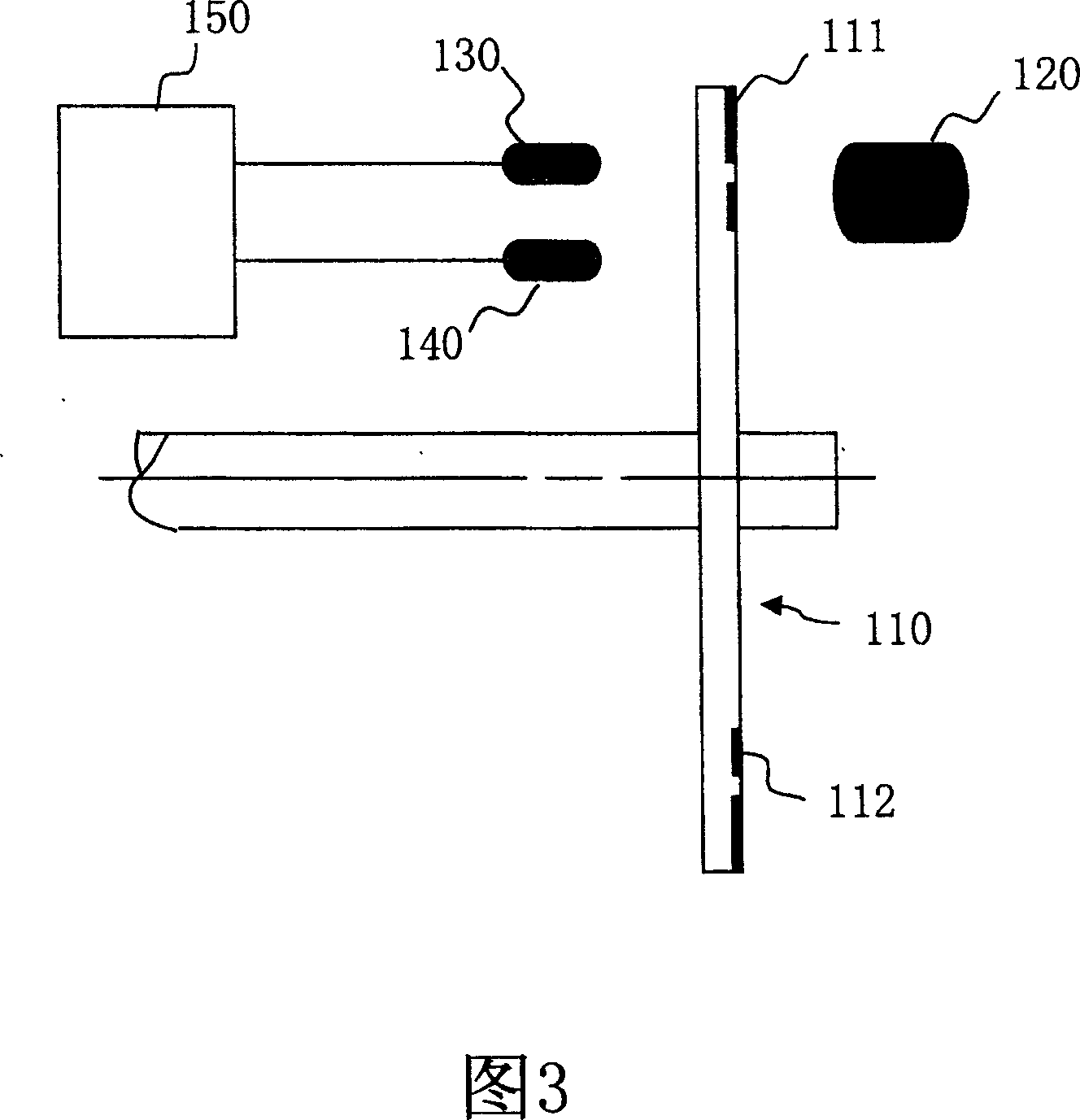
[0069] Please refer to FIG. 2 and FIG. 3 , the rotary optical encoder 100 provided by the present invention is applied to a permanent magnet motor 500 to provide the magnetic pole position of the rotor 510 . The rotary optical encoder 100 includes an optical transmitter 120 , an encoder wheel 110 , two optical sensors 130 and 140 , and a processing circuit 150 . Wherein, the code disc 110 is coupled to the rotating shaft 520 of the permanent magnet motor 500. When the rotor 510 rotates, the code disc 110 will be driven to rotate. The code disc 110 is regularly engraved with fine slits 111 and code tracks 112 to enable For light transmission, a light emitter 120 and two light sensors 130 and 140 are respectively installed on both sides of the code disc 110 . When the encoder disk 110 rotates, the light emitter 120 provides the light source, and the amount of light sensed by the light sensors 130 and 140 changes synchronously with the light-transmitting lines, and the light inte...


PUM


Abstract

This invention relates to optical coder used to output phase changing signals in permanent magnetic motor and the rotation optical coder comprises: one coder panel coupled to rotation axis with one coding rail composed of multiple areas, wherein the said area is located with first hole, second hole, third hole, forth hole, five hole, and six hole, wherein the first, second and third hole are separately relative to the six, five holes; one optical emission device to project light source; two light sensors located on the both sides of the coder panel to detect the light intensity; one process circuit connected to the light sensor to convert the light intensity into phase signals and to output phase signals.

Description

technical field [0001] The invention relates to a rotary optical encoder, in particular to a rotary optical encoder with the function of phase-commutation signal output. Background technique [0002] The rotary optical encoder is mainly used to detect the magnetic pole position of the rotor. Its main structure includes a light transmitter, a light receiver, a code wheel and a code plate in between, and a processing circuit. The desired signal output can be obtained by properly designing the pattern of the coding track on the coding disc and the coding chip. [0003] In the design of general servo motors, a rotary optical encoder is often used to detect its rotational position, speed and direction of rotation. If the servo motor is a brushless type, Hall devices are traditionally used to provide the required rotor position. signal to commutate the stator winding currents correctly. In order to save space and reduce costs, encoder manufacturers integrate the commutation func...

Claims


Application Information

Patent Timeline
Patent Type & Authority Patents(China)
IPC IPC(8): G01D5/34
Inventor 许宏成梁德生
Owner 台达绿色科技新加坡私人有限公司
Why Eureka
Try Eureka