Sewage treatment system capable of improving concentration of activated sludge, and technology of sewage treatment system

A sewage treatment system and activated sludge technology, applied in the direction of water/sludge/sewage treatment, water/sewage multi-stage treatment, chemical instruments and methods, etc., can solve the difficulty of maintaining microorganisms in biochemical reaction tanks and the surface load of gravity sedimentation tanks low, poor sludge thickening effect, etc., to achieve the effect of saving land acquisition costs, ensuring the effect of air flotation, and reducing energy consumption

Inactive Publication Date: 2014-01-15
SHANGHAI MUNICIPAL ENG DESIGN INST GRP
View PDF11 Cites 2 Cited by
  • Summary
  • Abstract
  • Description
  • Claims
  • Application Information

AI Technical Summary

Problems solved by technology

[0006] In view of the gravity sedimentation used in the existing sewage treatment process, the solid-liquid separation efficiency is low, and the sludge concentration effect is poor, which makes it difficult for the microorganisms in the biochemical reaction tank to maintain a high concentration, resulting in low treatment capacity; and the gravity sedimentation tank in the sewage treatment system The problem of low surface load and large floor area, the purpose of the present invention is to provide a sewage treatment system and its process that can increase the concentration of activated sludge, which saves construction land, low energy consumption for operation, good solid-liquid separation effect, and water discharge The water quality is stable and high-quality, which can be used in the new construction of continuous flow sewage treatment plants

Method used


Image

  • Sewage treatment system capable of improving concentration of activated sludge, and technology of sewage treatment system
  • Sewage treatment system capable of improving concentration of activated sludge, and technology of sewage treatment system

Examples


Embodiment 1

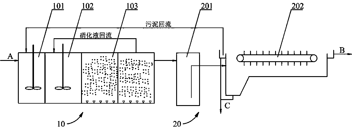
[0028] Embodiment one: the following combination figure 2 The sewage treatment system of this embodiment is described, which includes a denitrification and phosphorus removal reaction unit 10 and a solid-liquid separation unit 20 connected in sequence. Wherein, the nitrogen and phosphorus removal reaction unit 10 includes an anaerobic zone 101 , anoxic zone 102 and an aerobic zone 103 connected in sequence, and the aerobic zone 103 communicates with the input end of the anoxic zone 102 through a pipeline. The solid-liquid separation unit 20 includes a deep dissolved air tank 201 and an air flotation tank 202 connected in sequence. The output end of the aerobic zone 103 communicates with the input end of the deep dissolved gas tank 201 . Further, the air flotation tank 202 communicates with the input end of the anaerobic zone 101 through a pipeline.

[0029] In the denitrification and phosphorus removal reaction unit 10, the input end of the anaerobic zone 101 is connected w...

Embodiment 2

[0036] Embodiment two: combine below figure 2 Illustrate the sewage treatment process of present embodiment, comprise the steps:

[0037] 1. Anaerobic phosphorus release reaction: The sewage first enters the anaerobic zone 101, and the sewage to be treated is mixed with the concentrated sludge returned to the anaerobic zone 101 from the air flotation tank 202, and the residence time is 1.5h, and the anaerobic phosphorus release reaction occurs; the activated sludge The phosphorus-accumulating bacteria in the water degrade the phosphorus-accumulating particles (poly-P) in the body to generate energy and release phosphate. At the same time, the phosphorus-accumulating bacteria absorb short-chain fatty acids in sewage to form PHB and store them in the cells.

[0038] Two, denitrification reaction: the effluent of anaerobic zone 101 enters anoxic zone 102, and the nitrification liquid that flows back to anoxic zone 102 with aerobic zone 103 carries out denitrification and denitri...

Embodiment 3

[0045] Example Three: Combining figure 2 Illustrate the sewage treatment process of the present embodiment, different from embodiment two, in step four, the depth of dissolved air deep pool 201 is 30m, and the air supply position of air compressor is 20m away from liquid surface; In step five, activated sludge The reflux ratio was 100%.

[0046] Based on the concentration of activated sludge in the air flotation tank of 20000mg / L, when the reflux ratio is 100%, according to the above formula, the concentration of concentrated sludge in the denitrification and phosphorus removal reaction unit is 10000mg / L.


PUM

PropertyMeasurementUnit
depthaaaaaaaaaa
concentrationaaaaaaaaaa

Abstract

The invention provides a sewage treatment system capable of improving concentration of activated sludge, and a technology of the sewage treatment system, and relates to the technical field of sewage treatment. The sewage treatment system and the technology aim at solving the problems that the existing sewage treatment technology is low in solid-liquid separation efficiency and poor in sludge thickening effect, microorganism in a biochemical reaction tank difficultly maintains higher concentration, the treatment capacity is low, and a gravity sedimentation tank in a treatment system is low in surface load and large in floor area. The system comprises a denitrification and dephosphorization reaction unit and a solid-liquid separation unit connected in series with the denitrification and dephosphorization reaction unit, wherein the denitrification and dephosphorization reaction unit comprises an anaerobic zone, an anoxic zone and an aerobic zone which are sequentially communicated; an input end of the aerobic zone is communicated with an input end of the anoxic zone by a pipeline; the solid-liquid separation unit comprises a dissolved air deep tank and a flotation tank which are sequentially communicated; and an output end of the aerobic zone is communicated with an input end of the dissolved air deep tank. The technology comprises the steps of 1, anaerobic phosphorus release reaction, 2, denitrification reaction, 3, carbon oxidization, aerobic phosphorus absorption and nitration reaction, 4, deep tank air dissolution, and 5, solid-liquid separation. The system and the technology are particularly suitable for new construction of a continuous flow sewage treatment plant.

Description

technical field [0001] The invention relates to the technical field of sewage treatment, in particular to a sewage treatment system capable of increasing the concentration of activated sludge and a process thereof. Background technique [0002] At present, my country is in a period of rapid industrialization and urbanization, urban land prices continue to rise, and construction land is in short supply. Conservation of land is not only forced by factor constraints, but also a long-term survival strategy. Only when the economy grows steadily and a new way of building land for sewage treatment plants with less land occupation and high land use efficiency can we continue to promote urbanization and realize The goal of building a resource-saving and environment-friendly society. [0003] The sewage treatment system and its process for efficient nitrogen and phosphorus removal with short development time and small footprint have always been the focus of research in the field of s...

Claims


Application Information

Patent Timeline
Patent Type & Authority Applications(China)
IPC IPC(8): C02F9/14
Inventor 邹伟国沈昌明贺晓红陈嫣
Owner SHANGHAI MUNICIPAL ENG DESIGN INST GRP
Why Eureka
Try Eureka