
A swing arm mechanism for reciprocating and moving wall and floor tiles

A technology of reciprocating swing, wall and floor tiles, which is applied to conveyor objects, transportation and packaging, etc., can solve the problems of increasing the use and maintenance cost of the swing arm device, difficult to achieve positioning of the end of the swing arm, and affecting the reliability of the swing device. Simple mechanical structure and electrical control method, improve motion accuracy, and relieve impact load effect

Active Publication Date: 2017-03-01
佛山市鼎吉包装技术有限公司
View PDF7 Cites 0 Cited by
  • Summary
  • Abstract
  • Description
  • Claims
  • Application Information

AI Technical Summary

Problems solved by technology

Due to the certain working gap between the rotor parts of the reducer, there is a certain free space in the swing angle of the swing arm, which makes it difficult to achieve precise positioning at the end of the swing arm
Moreover, with the wear and tear of the rotor parts of the reducer, the above-mentioned free angle space of the swing arm will gradually increase, seriously affecting the reliability of the long-term operation of the swing device.
In addition, due to the way that the reducer directly drives the swing arm, the output rotor of the reducer will always only have part of the arc section involved in the working stroke. This uneven workload will seriously weaken the service life of the reducer and increase the use of the swing arm device. and maintenance costs

Method used


Image

  • A swing arm mechanism for reciprocating and moving wall and floor tiles
  • A swing arm mechanism for reciprocating and moving wall and floor tiles
  • A swing arm mechanism for reciprocating and moving wall and floor tiles

Examples


Embodiment Construction

[0015] The present invention will be further described below in conjunction with a specific embodiment:

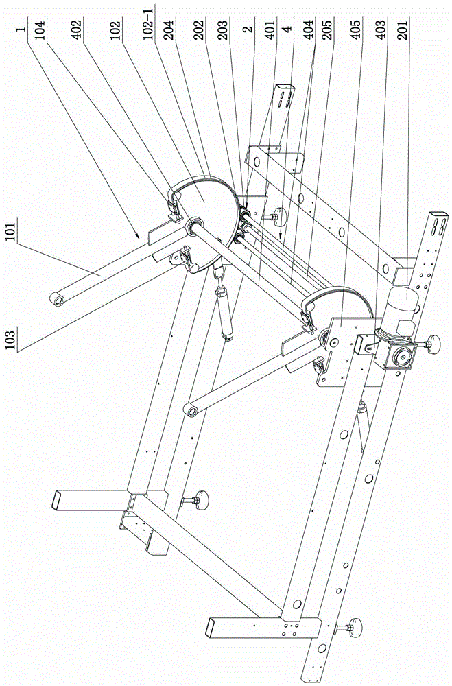
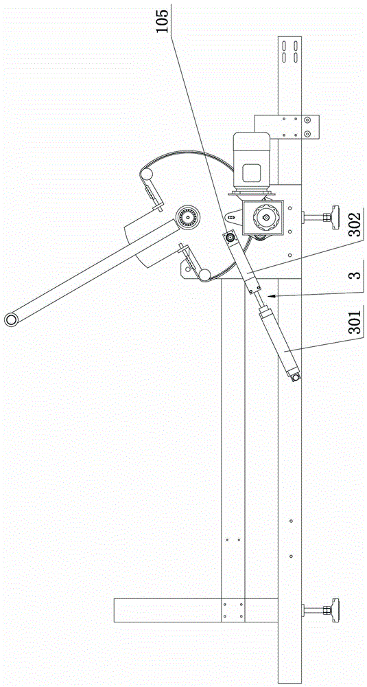
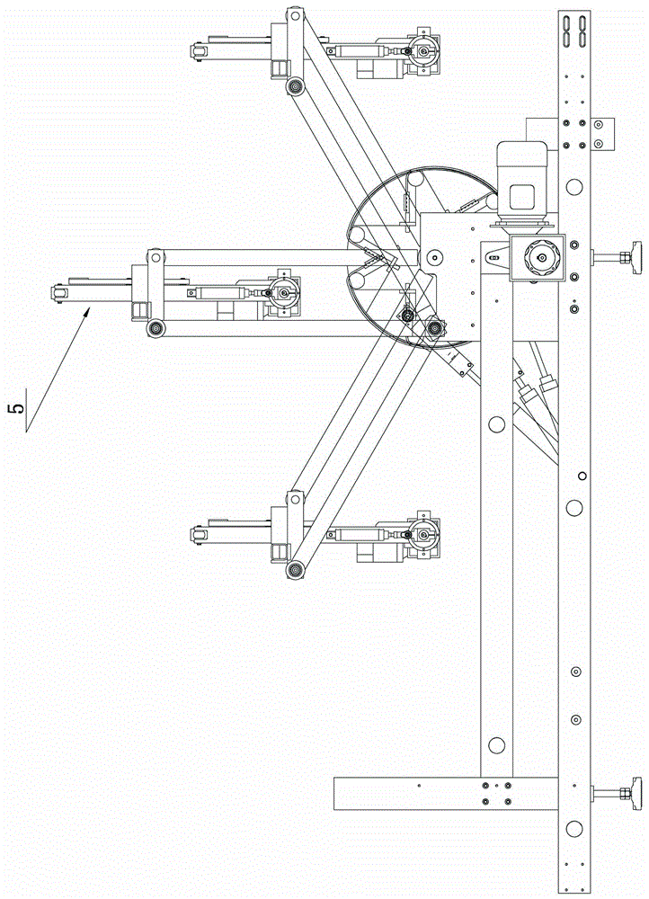
[0016] See attached Figure 1 to Figure 3 As shown, a swing arm structure for reciprocatingly swinging and transferring wall and floor tiles described in this embodiment. It includes a swing arm assembly 1, a swing arm drive assembly 2, a base 4 and a wall and floor tile gripping device 5. The swing arm assembly 1 includes a swing arm 101 on both sides, a swing wheel 102, a timing belt joint 103, and a timing belt splint 104; the swing arm drive assembly 2 includes a reduction motor 201, a drive shaft 205, and timing belt drive wheels on both sides 202, the timing belt guide wheel 203 and the timing belt 204; the base 4 includes a shaft 401 and a bearing 402 supporting the swing arm assembly 2, a set of support shafts 404 supporting the timing belt guide wheel 203, a bearing seat 405 supporting the drive shaft 205 and Fix the fixed seat 403 of the geared motor 201.

[0017] ...


PUM


Abstract

The invention relates to a swing arm mechanism capable of sending wall and floor tiles in a reciprocating and swinging mode. The swing arm mechanism comprises a swing arm assembly, a swing arm driving assembly, a base and a wall and floor tile grasping device. The swing arm assembly comprises a swing arm and a swinging wheel disc. The swing arm driving assembly comprises a speed reduction motor, a drive wheel, a guide wheel and a synchronization belt. The total center of gravity of the swing arm assembly and the wall and floor tile grasping device downwards falls from the highest point in the middle to the two sides to be adjacent to mutual symmetric limit positions. The swing arm mechanism is further provided with an air cylinder assisting assembly. The air cylinder assisting assembly comprises an air cylinder and a connection rod. When the total center of gravity of the swing arm assembly and the wall and floor tile grasping device is on the highest point and the air cylinder is located at the working limit position, the air cylinder works, one cavity is emptied and the other cavity is supplied with air. A local segment of the synchronization belt is fixed on the swinging wheel disc. The swinging wheel disc is a complete round wheel or a notched round wheel. The base comprises a shaft, a bearing, a supporting shaft and a fixed base. A swing arm is rapidly and accurately swung by means of a simple structure and a simple control manner, impact loads of the swing arm driving assembly are greatly reduced and the service life of the swing arm mechanism is effectively prolonged.

Description

Technical field [0001] The invention relates to the technical field of automatic sorting and offline of finished wall and floor tiles, in particular to a swing arm mechanism for reciprocatingly swinging and transferring wall and floor tiles. Background technique [0002] In the device for automatic sorting and offline of finished wall and floor tiles in the prior art, a geared motor is used to directly drive the mandrel of the swing arm. Since there is a certain working gap between the rotor parts of the reducer, there is a certain free space for the swing angle of the swing arm, which makes it difficult to achieve precise positioning at the end of the swing arm. Moreover, as the rotor components of the reducer work and wear, the above-mentioned free angle space of the swing arm will gradually increase, which seriously affects the long-term reliability of the swing device. In addition, because the reducer directly drives the swing arm, the output rotor of the reducer always has ...

Claims


Application Information

Patent Timeline
Patent Type & Authority Patents(China)
IPC IPC(8): B65G47/74B65G47/91
Inventor 彭智勇
Owner 佛山市鼎吉包装技术有限公司
Learn More