
Radar/infrared two-waveband frequency selective surface

A frequency-selective surface and dual-band technology, applied in waveguide devices, electrical components, circuits, etc., can solve the problem that square metal grid FSS cannot further improve optical transmittance, which is unfavorable for high-precision detection and observation imaging applications, Concentrated distribution of stray light and other issues, to achieve uniform distribution of diffracted light intensity, high optical transmittance, and suppress stray light

Active Publication Date: 2014-01-01
CHANGCHUN INST OF OPTICS FINE MECHANICS & PHYSICS CHINESE ACAD OF SCI
View PDF1 Cites 15 Cited by
  • Summary
  • Abstract
  • Description
  • Claims
  • Application Information

AI Technical Summary

Problems solved by technology

[0005] In order to solve the technical problems that the square metal grid FSS in the prior art cannot further improve the optical transmittance, the distribution of stray light is concentrated, and it is not conducive to the application in high-precision detection and observation imaging, the present invention provides a radar / infrared dual Band FSS

Method used


Image

  • Radar/infrared two-waveband frequency selective surface
  • Radar/infrared two-waveband frequency selective surface
  • Radar/infrared two-waveband frequency selective surface

Examples


preparation example Construction

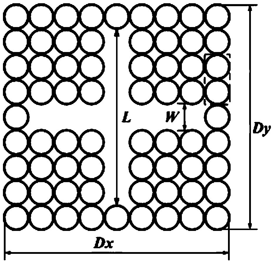
[0026] The preparation process of the radar / infrared dual-band FSS of the present invention is basically the same as the preparation process of the existing square metal grid FSS, only need to add the corresponding part of the cross hole on the round hole type or hexagonal metal grid film plate. Can.

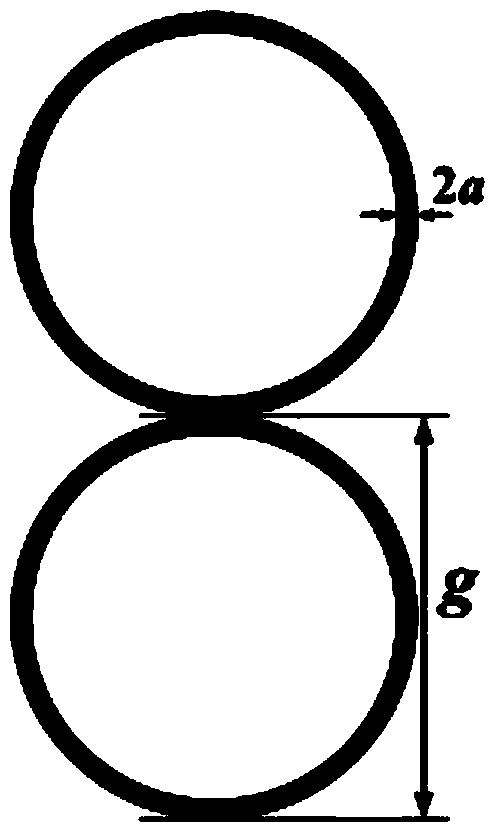
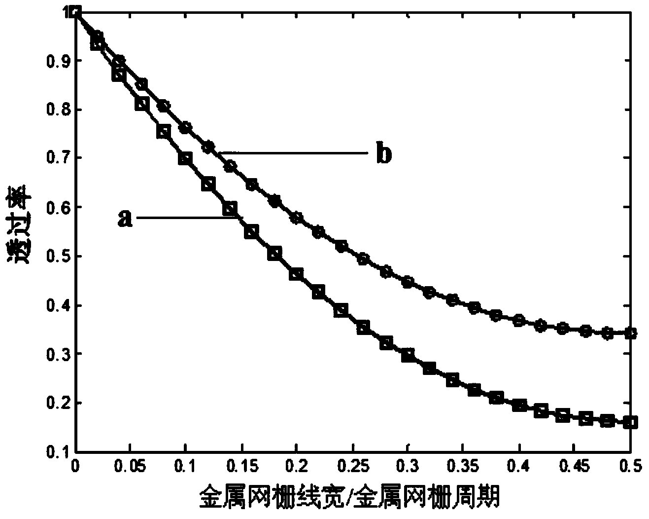
[0027] Apply Kohin research conclusion to radar / infrared dual-band FSS of the present invention, then the optical transmittance Ta of radar / infrared dual-band FSS is:

[0028] T a = ( 1 - πag - a 2 π g 2 ) 2 ( 1 - 2 km - ...

Embodiment 1

[0031] Such as Figure 4 As shown, according to the Fraunhofer diffraction theory, the scalar diffraction model of the circular hole metal grid FSS under oblique illumination is established, Figure 4 , the parallel light illuminates E along z(z 1 ) axis propagation, the coordinate before FSS tilt is x 1 o 1 the y 1 , the coordinate after FSS tilt is x 1 'o 1 the y 1 ’, the distance between any point Q on the FSS and the point P on the observation surface xoy is represented by r, and the observation point P and the origin of the FSS coordinates o 1 r o It means that through the Fourier transformation of the pupil, the distribution of diffracted light intensity on the image surface under different incident angles is obtained, such as Figure 5 shown by Figure 4 with Figure 5 Calculate the high-order diffraction energy distribution of the circular hole metal grid FSS;

[0032] MgF with a thickness of 3.82mm, a relative permittivity of 4.803, and a tangent loss value...


PUM


Abstract

The invention discloses a radar / infrared two-waveband frequency selective surface which solves the technical problems that a latticed metal mesh FSS in the prior art cannot further improve optical transmittance, the distribution of stray light is centralized, and the application in high-precision detection and imaging observation is not facilitated, and belongs to the technical field of electromagnetic shielding. The radar / infrared two-waveband FSS is a cross-hole-shaped periodic array on a metal mesh, the metal mesh is a round-hole-shaped metal mesh or a hexagonal metal mesh, the periods of cross hole shapes are the integer multiples of the period of the metal mesh, and each cross hole shape meets the two following constraint conditions that the slit width of the cross hole shapes is the integer multiples of the period of the metal mesh minus the wire width of the metal mesh; the difference between the slit length of the cross hole shapes and the slit width of the cross hole shapes is the even times of the period of the metal mesh. The radar / infrared two-waveband FSS is higher in optical transmittance, more even in diffraction light distribution and capable of effectively restraining the stray light.

Description

technical field [0001] The invention relates to a radar / infrared dual-band frequency selective surface, which belongs to the technical field of electromagnetic shielding. Background technique [0002] The radar / infrared imaging composite guidance technology is to accurately guide the aircraft to the vicinity of the target through the large-scale search of the radar seeker, so that the target enters the range of the infrared imaging seeker, and then utilizes the high-resolution characteristics of the infrared imaging seeker Accurate target recognition. The electromagnetic shielding technology of the compound guidance dome is the key technology of the compound guidance, its performance directly affects the combat performance and hit accuracy of the missile, and even determines whether the whole system can work normally. The difficulty in realizing the technical approach of the composite guidance hood is to achieve strong electromagnetic shielding efficiency while only allowin...

Claims


Application Information

Patent Timeline
Patent Type & Authority Applications(China)
IPC IPC(8): G02B5/18H01P1/20
Inventor 徐念喜高劲松
Owner CHANGCHUN INST OF OPTICS FINE MECHANICS & PHYSICS CHINESE ACAD OF SCI
Learn More