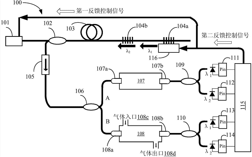
Fiber bragg grating combined optical fiber laser gas detection system with reference cavity compensation

A gas detection system, fiber laser technology, applied in color/spectral characteristic measurement, instruments, measuring devices, etc., can solve problems such as unsatisfactory results, inability to eliminate measurement errors, and inability to strictly eliminate laser fluctuations, to eliminate measurement errors, compact effect

Active Publication Date: 2014-01-01
BEIJING INFORMATION SCI & TECH UNIV
View PDF6 Cites 25 Cited by
  • Summary
  • Abstract
  • Description
  • Claims
  • Application Information

AI Technical Summary

Problems solved by technology

However, this measurement scheme cannot eliminate the measurement error caused by the unstable wavelength of the detection light, and this error cannot be ignored in actual measurement
Therefore, in the prior art, the differential absorption method has been improved. The commonly used improvement methods are to realize the stable wavelength of the laser by achieving stable current and stable temperature. However, this method is passively adjusted and cannot strictly eliminate the laser fluctuations, so the improved effect is not ideal

Method used


Image

  • Fiber bragg grating combined optical fiber laser gas detection system with reference cavity compensation
  • Fiber bragg grating combined optical fiber laser gas detection system with reference cavity compensation
  • Fiber bragg grating combined optical fiber laser gas detection system with reference cavity compensation

Examples


Embodiment Construction

[0024]Hereinafter, embodiments of the present invention will be described with reference to the accompanying drawings. In the drawings, the same reference numerals represent the same or similar components, or the same or similar steps.

[0025] The objects and functions of the present invention and methods for achieving the objects and functions will be clarified by referring to the exemplary embodiments. However, the present invention is not limited to the exemplary embodiments disclosed below; it can be implemented in various forms. The essence of the description is only to help those skilled in the relevant art comprehensively understand the specific details of the present invention.

[0026] The present invention is described in detail in conjunction with schematic diagrams. When describing the embodiments of the present invention in detail, for the convenience of explanation, the cross-sectional view showing the structure of the device will not be partially enlarged acco...


PUM


Abstract

The invention provides a fiber bragg grating combined optical fiber laser gas detection system with reference cavity compensation. The fiber bragg grating combined optical fiber laser gas detection system comprises an optical fiber laser, an optical isolator, a coupler, a second wavelength division multiplexer, a third wavelength division multiplexer, a first photoelectric detector, a second photoelectric detector, a third photoelectric detector, a fourth photoelectric detector, and a feedback control unit which are sequentially connected, wherein the optical fiber laser comprises a laser diode pumping source, a first wavelength division multiplexer, an active optical fiber, a first fiber bragg grating and a second fiber bragg grating and respectively emits a first wavelength laser beam and a second wavelength laser beam, the coupler is used for carrying out power beam splitting on light beams, the light beams subjected to the beam splitting are respectively introduced into a reference air chamber and a detection air chamber, the second wavelength division multiplexer is connected with the reference air chamber, the third wavelength division multiplexer is connected with the detection air chamber, the first photoelectric detector and the second photoelectric detector are connected to the second wavelength division multiplexer, the third photoelectric detector and the fourth photoelectric detector are connected to the third wavelength multiplexer to generate a first optical intensity signal, a second optical intensity signal, a third optical intensity signal and a fourth optical intensity signal; the feedback control unit receives the first optical intensity signal, the second optical intensity signal, the third optical intensity signal and the fourth optical intensity signal and uses a comparing result as a feedback signal for regulating the optical fiber laser.

Description

technical field [0001] The invention relates to the field of fiber lasers, in particular to a gas detection system and method for a dual-wavelength combined fiber laser with reference cavity compensation for realizing gas concentration measurement. Background technique [0002] Each gas molecule has its own characteristic absorption spectrum, so when the emission spectrum of the light source overlaps with the gas absorption spectrum, the gas can be determined by measuring the transmitted light intensity by using the light emitted by a narrow-band light source or a laser light source. concentration. Since the spectral line width of general light sources is wide, and the absorption spectral lines of some gases are very narrow, the optical power changes after passing through the gas chamber are not obvious, resulting in low measurement sensitivity. The laser light source has a narrow output spectral line, which is suitable for measuring various gases. [0003] Laser plays an ...

Claims


Application Information

Patent Timeline
Patent Type & Authority Applications(China)
IPC IPC(8): G01N21/39
CPCG01N21/274G01N21/3504G01N21/39G01N33/0036G01N2021/399
Inventor 骆飞祝连庆董明利何巍张荫民
Owner BEIJING INFORMATION SCI & TECH UNIV
Why Eureka
Try Eureka