
Thermal field uniform distribution device for temperature and humidity environment testing equipment with uniformity of less than 0.5 degree centigrade grade

An environmental test, uniformity technology, applied in heating or cooling equipment, laboratory utensils, shells or chambers, etc., can solve problems such as the uniformity range of the small temperature field, achieve a small temperature change range, and facilitate the disassembly and cleaning of equipment. Effect

Inactive Publication Date: 2014-01-01
多禾试验设备(上海)有限公司
View PDF1 Cites 9 Cited by
  • Summary
  • Abstract
  • Description
  • Claims
  • Application Information

AI Technical Summary

Problems solved by technology

[0002] The existing constant temperature and humidity test chamber usually adopts a refrigeration system composed of a condenser, a compressor, a capillary tube, an evaporator and connecting pipes. The capillary tube is connected between the condenser and the evaporator, and the condenser, compressor, and evaporator are sequentially used Pipe connection, the temperature field uniformity of this test equipment meets the national standard of 2 degrees Celsius, but as the requirements of the existing test conditions become more and more stringent, the temperature field uniformity range of 2 degrees Celsius is too large, and a smaller temperature field is required Field Uniformity Range

Method used


Image

  • Thermal field uniform distribution device for temperature and humidity environment testing equipment with uniformity of less than 0.5 degree centigrade grade
  • Thermal field uniform distribution device for temperature and humidity environment testing equipment with uniformity of less than 0.5 degree centigrade grade

Examples


Embodiment Construction

[0015] In order to make the technical means, creative features, goals and effects achieved by the present invention easy to understand, the present invention will be further described below in conjunction with specific illustrations.

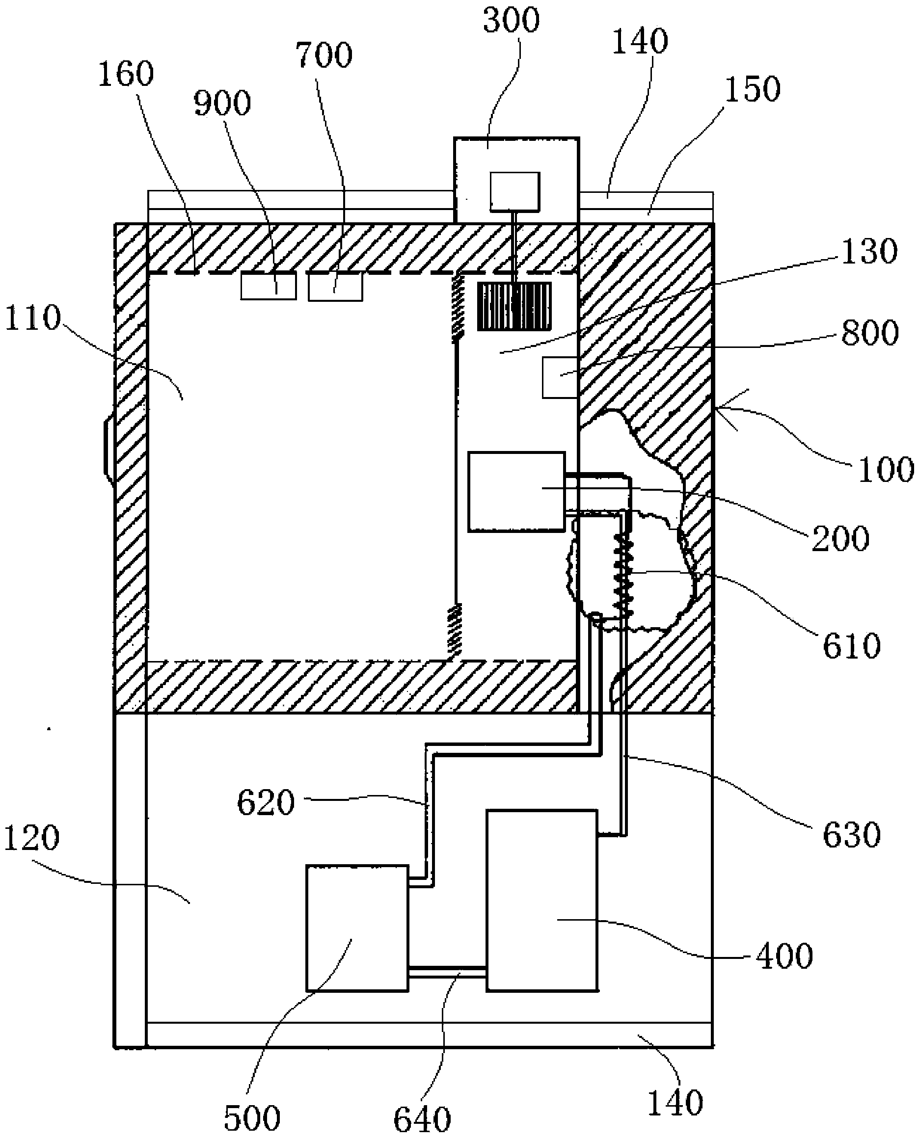
[0016] see figure 1 The temperature field uniform distribution device of the temperature and humidity environmental test equipment with uniformity less than 0.5 degrees Celsius is shown, including a box body 100 , the lower part of the box body 100 is an equipment room 120 , and the inner cavity of the box body 100 has a work room 110 and a circulating air duct 130 .

[0017] The top of the box body 100 is provided with an air circulation fan 300 communicating with the circulating air duct 130, the temperature and humidity sensor 700, the evaporator 200, the heater 800, and the humidifier 900 on the inner wall of the box body 100, wherein the evaporator 200 is arranged in the circulating air duct Within 130.

[0018] A refrigeration compressor ...


PUM


Abstract

The invention discloses a thermal field uniform distribution device for temperature and humidity environment testing equipment with the uniformity of less than a 0.5 degree centigrade grade. The thermal field uniform distribution device comprises a box body and an equipment room arranged on the lower part of the box body, wherein an inner cavity of the box body is provided with a working room and a circulating air flue; the thermal field uniform distribution device further comprises an air circulating fan, a temperature and humidity sensor, an evaporator, a heater, a humidifier, a refrigeration compressor and a condenser; uniform distribution plates are arranged on the left and right sides as well as the top and the bottom of the box body; an air returning plate is arranged at the top of the box body; the inner wall of the box body is provided with a double-layer insulating layer composed of a polyurethane insulating layer and an ultrafine glass fiber insulating layer; the temperature and humidity sensor, the evaporator, the heater, the humidifier and the refrigeration compressor are controlled and connected by a PLC (Programmable Logic Controller) control system; the PLC control system is internally provided with a temperature control system for controlling the temperature uniformity to be 0.5 degree centigrade so as to control the temperature uniformity in the working room to be within 0.5 degree centigrade.

Description

technical field [0001] The invention relates to the technical field of temperature and humidity test equipment, in particular to a temperature field uniform distribution device for temperature and humidity environmental test equipment with a uniformity less than 0.5 degrees Celsius. Background technique [0002] The existing constant temperature and humidity test chamber usually adopts a refrigeration system composed of a condenser, a compressor, a capillary tube, an evaporator and connecting pipes. The capillary tube is connected between the condenser and the evaporator, and the condenser, compressor, and evaporator are sequentially used Pipeline connection, the temperature field uniformity of this test equipment meets the national standard of 2 degrees Celsius, but as the requirements of the existing test conditions become more and more stringent, the temperature field uniformity range of 2 degrees Celsius is too large, and a smaller temperature field is required field uni...

Claims


Application Information

Patent Timeline
Patent Type & Authority Applications(China)
IPC IPC(8): B01L1/00B01L7/00
Inventor 马德金马徳理范丽娟王秀丽姜允张磊
Owner 多禾试验设备(上海)有限公司
Learn More