CAN bus analysis system with bus error analysis function
A CAN bus and bus error technology, applied in the field of automation technology and fault diagnosis, can solve problems such as real-time monitoring of faults, real-time error analysis, etc., and achieve the effect of compact structure and easy implementation
- Summary
- Abstract
- Description
- Claims
- Application Information
AI Technical Summary
Problems solved by technology
Method used
Image

Examples
Embodiment
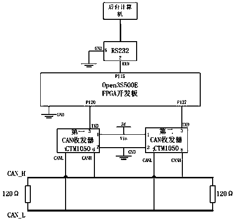
[0024] The operating frequency of the Open3S500E FPGA development board in the CAN bus analysis system with bus error analysis function is 50MHz; The 3-pin of the first CAN transceiver CTM1050 is connected, the P127 input / output port of the Open3S500E FPGA development board is connected to the 3-pin of the second CAN transceiver CTM1050, the Open3S500E FPGA development board uses JTAG to burn the program, the first CAN transceiver Pin 2 of CTM1050 and the second CAN transceiver CTM1050 are grounded at the same time, pin 1 is connected to 5V positive voltage at the same time, pin 7 is used to connect CAN_L of CAN bus, pin 6 is used to connect CAN_H of CAN bus, all groundings are the same ; RS232 serial port is used to send data to the background computer.
[0025] The resistance of the terminal resistance at both ends of the CAN bus is 120Ω, the bus communication rate is set to 500kbps, the sampling period is 100ns, and the serial port baud rate is 115200bps. The CAN bus error ...
PUM
 Abstract
Description
Claims
Application Information
 - R&D
- Intellectual Property
- Life Sciences
- Materials
- Tech Scout
- Unparalleled Data Quality
- Higher Quality Content
- 60% Fewer Hallucinations
Browse by: Latest US Patents, China's latest patents, Technical Efficacy Thesaurus, Application Domain, Technology Topic, Popular Technical Reports.
© 2025 PatSnap. All rights reserved.Legal|Privacy policy|Modern Slavery Act Transparency Statement|Sitemap|About US| Contact US: help@patsnap.com