
Controller and control method based on FPGA (Field Programmable Gate Array) of scanning ionic conductivity microscope

A technology of scanning ion conductance and control method, which is applied in the controller and control field of scanning ion conductance microscope, can solve the problems of slow control, less consideration of system architecture and human-computer interaction, long experimental imaging time, etc., and achieve volume reduction , miniaturization, and increased application range

Inactive Publication Date: 2013-12-25
XI AN JIAOTONG UNIV
View PDF6 Cites 4 Cited by
  • Summary
  • Abstract
  • Description
  • Claims
  • Application Information

AI Technical Summary

Problems solved by technology

In the scanning ion conductance microscope experiment, the tip of the probe should be moved down vertically to the nanometer distance from the sample surface. The traditional controller focuses on the construction of the protection circuit or the drive circuit, mainly through the feed control of piezoelectric ceramics. The scanning observation experiment showed problems such as slow control and long imaging time of the experiment, and less consideration was given to the system architecture and human-computer interaction

Method used


Image

  • Controller and control method based on FPGA (Field Programmable Gate Array) of scanning ionic conductivity microscope
  • Controller and control method based on FPGA (Field Programmable Gate Array) of scanning ionic conductivity microscope
  • Controller and control method based on FPGA (Field Programmable Gate Array) of scanning ionic conductivity microscope

Examples


Embodiment Construction

[0037] The present invention will be described in further detail below in conjunction with the accompanying drawings.

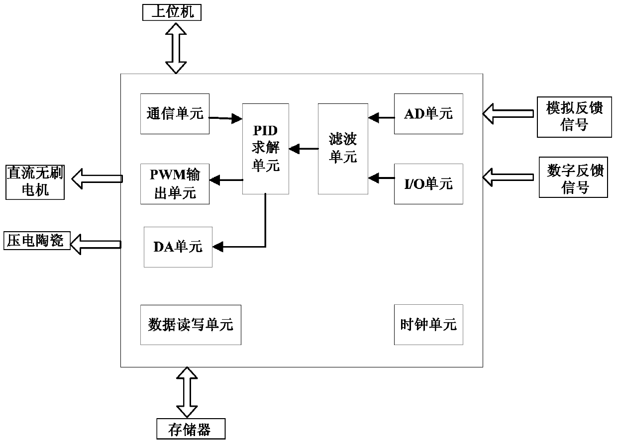
[0038] Such as figure 1 As shown, the controller of the FPGA-based scanning ion conductance microscope provided by the present invention is divided into 9 processing units that operate in parallel with each other: clock unit, I / O unit, communication unit, DA unit, AD unit, filter unit, data Read and write unit, PID solving unit, PWM output unit, where AD unit and I / O unit are signal acquisition units, PWM output unit and DA unit are output units. The communication unit communicates with the host computer through the peripheral communication interface to obtain the preset control target, and transmits the control target to the PID solving unit. At the same time, the human-computer interaction communication can be completed through the external keyboard, and the real-time work of the scanning observation experiment can be read out through the host computer. The...


PUM


Abstract

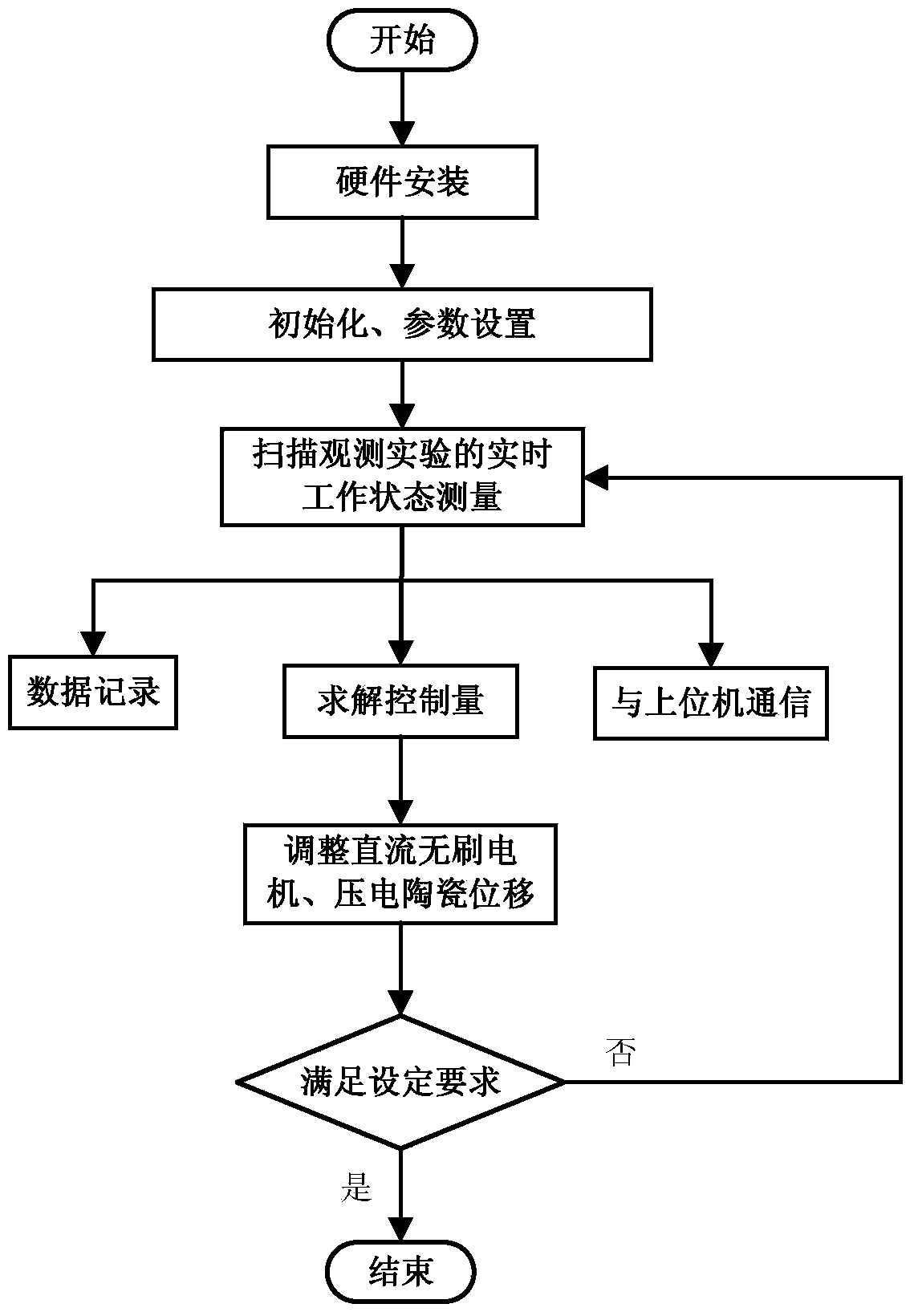
The invention provides a controller and a control method based on a FPGA (Field Programmable Gate Array) of a scanning ionic conductivity microscope. The controller comprises a communication unit and a clock unit, wherein the communication unit is respectively connected to an upper computer and a PID (Proportion Integration Differentiation) solving unit; the PID solving unit is respectively connected to a signal acquisition unit, a PWM (Pulse-Width Modulation) output unit and a DA (Destination Address) unit; the clock unit is used for unifying time sequential routines. The control method comprises the steps that after parameters are initialized and set, the signal acquisition unit is used for acquiring feedback signals, the PID solving unit is used for solving controlled quantity, when the values of the feedback signals are greater than the threshold values of the feedback signals, the PWM output unit is used for controlling a brushless direct current motor to drive a probe and a tray to move, when the values of the feedback signals are less than the threshold values of the feedback signals, the DA unit is used for controlling a piezoelectric ceramic to drive the tray to move, meanwhile, the feedback signals and the controlled quantity are transmitted to the upper computer for display, and the steps are repeated till a control objective is satisfied or an end command is received. The controller is used for the control on a sample scanning image and is small in size; the robustness and intelligence of the controller are improved; the observation imaging speed can be increased under the condition of maintaining the resolution ratio.

Description

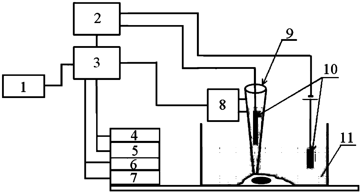
technical field [0001] The invention relates to the field of control of brushless DC motors and piezoelectric ceramics, in particular to a controller and a control method of an FPGA-based scanning ion conductance microscope. Background technique [0002] Scanning ion conductance microscopy is a scanning probe microscopy technique whose principle is as follows figure 2 Shown: An Ag / AgCl electrode is placed in an electrolyte-filled glass micropipette as a scanning probe, and a non-conductive sample is placed at the bottom of an electrolyte reservoir. As the glass micropipette approaches the sample surface, the ionic conductance decreases due to the reduced space that restricts the free flow of ions into the glass micropipette tip. When the glass micropipette probe is scanning close to the sample surface, the change of conductance between the electrode in the glass micropipette and another Ag / AgCl electrode in the electrolytic cell is monitored in real time, and the probe is m...

Claims


Application Information

Patent Timeline
Patent Type & Authority Applications(China)
IPC IPC(8): G05D3/12G01Q10/04
Inventor 庄健金鹏
Owner XI AN JIAOTONG UNIV
Learn More