
Photoisomerization reflecting mirror system

A photoisomerization and mirror technology, applied in the field of aerospace optical remote sensing, can solve the problems of increased weight and volume, increased development cost of remote sensors, and the difficulty of optical system accuracy to meet optical imaging, achieving light weight, saving development costs, simple structure

Active Publication Date: 2013-12-25
BEIJING RES INST OF SPATIAL MECHANICAL & ELECTRICAL TECH
View PDF5 Cites 8 Cited by
  • Summary
  • Abstract
  • Description
  • Claims
  • Application Information

AI Technical Summary

Problems solved by technology

[0002] With the rapid development of aerospace technology and the continuous improvement of military and civilian requirements for space remote sensing, it has become an inevitable trend to greatly increase the caliber and focal length of remote sensors. Therefore, the weight and volume of remote sensors have also doubled, leading to the development of remote sensors The substantial increase in cost has also brought great challenges to the launch. Therefore, it is necessary to reduce the size and weight of the remote sensor to save development and launch costs.
On the other hand, with the increase of the aperture of the remote sensor, the accuracy of the optical system is difficult to meet the requirements of optical imaging, especially visible light imaging. Therefore, it is necessary to adjust the accuracy of the optical system of the remote sensor on-orbit in real time to meet the system requirements.

Method used


Image

  • Photoisomerization reflecting mirror system
  • Photoisomerization reflecting mirror system
  • Photoisomerization reflecting mirror system

Examples


Embodiment Construction

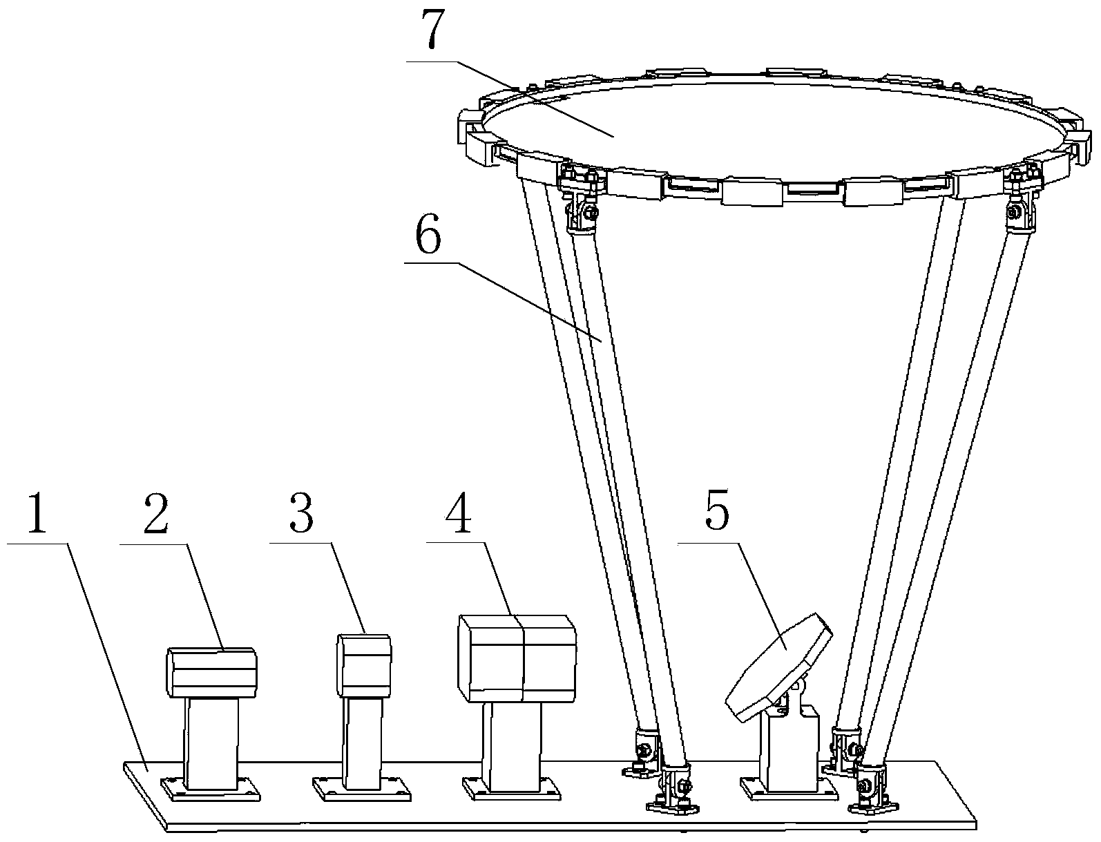
[0016] The invention provides a light-weight photoisomerism reflector system, which is installed in the optical-mechanical system of the remote sensor, used as a reflector for space optical remote sensors, and can be made into a large-diameter reflector, which is light in weight and can control light through polarization The surface shape of the heterogeneous thin film mirror meets the imaging requirements of the optical system.

[0017] The light-duty photoisomerism mirror system adopts a composite film made of a new type of high stability and high uniformity azobenzene derivatives and polyimide film, and utilizes the photoisomerization characteristics of azobenzene derivatives by changing The energy, spot size and polarization direction of the polarized light incident on the mirror surface can be adjusted in real time to change the surface shape of the film mirror.

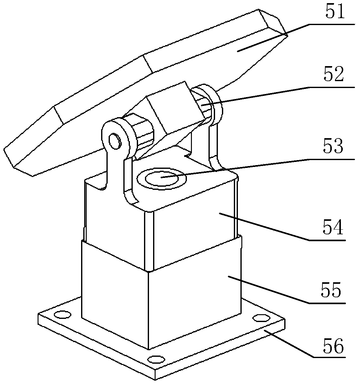
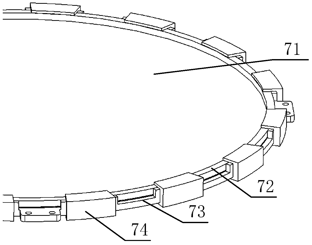
[0018] like figure 1 As shown, the present invention includes a substrate 1 , a laser 2 , a beam expander 3 ...


PUM


Abstract

Disclosed is a photoisomerization reflecting mirror system. Azobenzene derivative composite films having photoisomerization features are adopted as materials of a reflecting mirror, and the surface shape of the film mirror is adjusted through the mode that the irradiation direction, time and power of polarized light to the film mirror are controlled to satisfy imaging precision requirements of an optical system. The photoisomerization reflecting mirror system mainly comprises a film reflecting mirror assembly, a reflecting mirror assembly supporting structure, a scanning device, a polarization and energy control device, a beam expansion device and a laser device; laser emitted by the laser device can be converted to light beams satisfying system control requirements through the beam expansion device and the polarization and energy control device; the scanning device adjusts the directions of the light beams, irradiates appointed regions and adjusts the surface shape of the reflecting mirror through the photoisomerization features of the materials. The photoisomerization reflecting mirror system has the advantages of being light and controllable in surface shape precision, and can be made into a large-diameter reflecting mirror, be applied to space remote sensors, reduce weights of the remote sensors and save the development cost of the remote sensors.

Description

technical field [0001] The invention belongs to the field of aerospace optical remote sensing and relates to an ultra-light mirror system for space remote sensors, which is suitable for the development requirements of future light remote sensors. Background technique [0002] With the rapid development of aerospace technology and the continuous improvement of military and civilian requirements for space remote sensing, it has become an inevitable trend to greatly increase the caliber and focal length of remote sensors. Therefore, the weight and volume of remote sensors have also doubled, leading to the development of remote sensors The substantial increase in cost has also brought great challenges to the launch. Therefore, it is necessary to reduce the size and weight of the remote sensor to save development and launch costs. On the other hand, with the increase of the aperture of the remote sensor, the accuracy of the optical system is difficult to meet the requirements of ...

Claims


Application Information

Patent Timeline
IPC IPC(8): G02B7/198G02B26/08G02B5/08G02B27/28
Inventor 苏云金建高阮宁娟王小勇杨秉新吴宪珉
Owner BEIJING RES INST OF SPATIAL MECHANICAL & ELECTRICAL TECH
Learn More