Special catalytic combustion bed for industrial volatile organic pollutants in PM2.5

An organic pollutant, catalytic combustion bed technology, applied in the combustion, combustion method, combustion type, etc. of catalytic materials, can solve the problems of low heat recovery and utilization efficiency, large heat loss, high temperature, improve combustion efficiency and purify rate, temperature compensation uniform, overcoming the effect of high temperature

Inactive Publication Date: 2015-09-30
赛智环保科技(天津)有限公司
View PDF6 Cites 0 Cited by
  • Summary
  • Abstract
  • Description
  • Claims
  • Application Information

AI Technical Summary

Problems solved by technology

[0002] With the enhancement of people's awareness of environmental protection, people pay more and more attention to air pollution, especially the recent frequent smog weather, which makes PM2.5 more concerned, and industrial volatile organic pollutants in PM2.5 are harmful to people The most harmful pollutants to the body. At present, the catalytic combustion bed is the most used to treat industrial volatile organic pollutants. The catalytic combustion bed is usually made of heat-resistant steel plates or industrial kiln masonry materials. The existing catalytic In the combustion bed structure, the air inlet and the air outlet are located at the upper and lower ends of the catalytic combustion bed. Although the existing structure can realize catalytic combustion, there are the following problems: 1. The structure of the catalytic combustion bed furnace itself has a large heat loss, and the efficiency of heat recovery and utilization Low; 2. The temperature in the structure of the catalytic combustion bed furnace is uneven, and the overall temperature is high in the center and low in the edge, which reduces the combustion efficiency of industrial volatile organic pollutants and affects the purification rate of catalytic combustion

Method used


Image

  • Special catalytic combustion bed for industrial volatile organic pollutants in PM2.5
  • Special catalytic combustion bed for industrial volatile organic pollutants in PM2.5
  • Special catalytic combustion bed for industrial volatile organic pollutants in PM2.5

Examples


Embodiment Construction

[0035] The present invention will be further described in detail below through the specific examples, the following examples are only descriptive, not restrictive, and cannot limit the protection scope of the present invention with this.

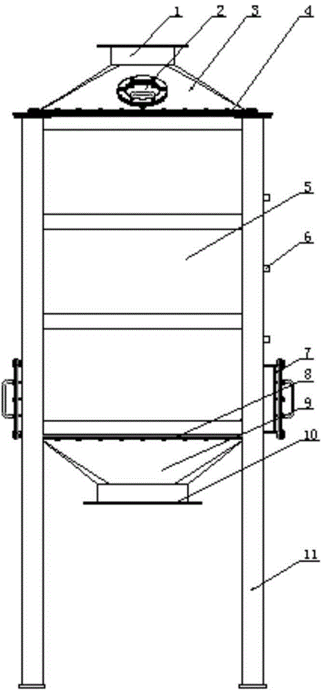
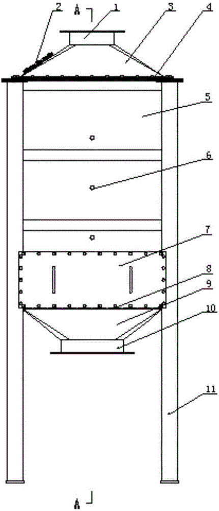
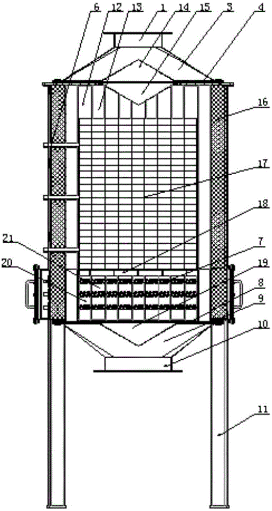
[0036]A catalytic combustion bed dedicated to industrial volatile organic pollutants in PM2.5, comprising an air intake hood 3, a furnace body 5 and an air outlet hood 9, a support frame 11 is arranged on the four corners of the outer wall of the furnace, and an explosion-proof vent is arranged on the air inlet hood. Pressure port 2, the upper end of the furnace body is fixed with an air inlet hood, the lower end of the furnace body is fixed with an outlet hood, the upper end of the air inlet hood is provided with a gas inlet 1, and the lower end of the air outlet hood is provided with a gas outlet 10. The furnace body includes a peripheral plate 22 of the furnace body and a fixed upper end thereof The upper end plate 4 of adorning and the lo...


PUM


Abstract

The invention relates to a catalytic combustion bed special for industrial volatilizable organic pollutants in PM 2.5 (particulate matter). A furnace inner enclosing plate is arranged in a furnace body outer enclosing plate; gas inlet paths and gas outlet paths are alternatively arranged between the furnace body inner enclosing plate and the furnace body outer enclosing plate; the inlet of each gas inlet path is arranged on an upper end plate; the outlet of each gas inlet path is arranged between a lower end plate and the furnace body inner enclosing plate; the inlet of each gas outlet path is arranged between the upper end plate and the furnace body inner enclosing plate; the outlet of each gas outlet path is arranged on the lower end plate; a gas inlet flow guiding shield is arranged on the middle, corresponding to the inlet of the gas inlet shield, of the upper end plate; a combustion gas flow guiding layer is arranged under the middle of the upper end plate; a heater is arranged in a furnace body corresponding to the outlets of the gas inlet paths; a catalyst layer is mounted on a catalyst support; a thermalcouple is mounted on the side wall of the furnace body. According to the catalytic combustion bed for the industrial volatilizable organic pollutants in PM 2.5, the heat efficiency of the catalytic combustion can be effectively improved, the heat loss can be reduced, the temperature in the catalytic combustion bed is more uniform during burning, and the burning efficiency and the purifying rate are improved.

Description

technical field [0001] The invention belongs to the field of catalytic combustion beds, in particular to a special catalytic combustion bed for industrial volatile organic pollutants in PM2.5. Background technique [0002] With the enhancement of people's awareness of environmental protection, people pay more and more attention to air pollution, especially the recent frequent smog weather, which makes PM2.5 more concerned, and industrial volatile organic pollutants in PM2.5 are harmful to people The most harmful pollutants to the body. At present, the catalytic combustion bed is the most used to treat industrial volatile organic pollutants. The catalytic combustion bed is usually made of heat-resistant steel plates or industrial kiln masonry materials. The existing catalytic In the combustion bed structure, the air inlet and the air outlet are located at the upper and lower ends of the catalytic combustion bed. Although the existing structure can realize catalytic combustion...

Claims


Application Information

Patent Timeline
Patent Type & Authority Patents(China)
IPC IPC(8): F23G7/07F23C13/00
Inventor 朱殿兴刘光明冯正赵崇光谷德明刘迎春
Owner 赛智环保科技(天津)有限公司
Why Eureka
Try Eureka