
Coal natural gas methanation technology and system thereof

A coal-to-natural gas and methanation technology, which is applied in the field of methanation process and its system, can solve the problems of high outlet temperature of the main methanation reactor, influence the service life of equipment, damage catalysts and equipment, etc., and achieves increased control means and adjustment Method, avoid metal dusting reaction, prevent contact effect

Active Publication Date: 2013-12-18
WUHUAN ENG
View PDF4 Cites 13 Cited by
  • Summary
  • Abstract
  • Description
  • Claims
  • Application Information

AI Technical Summary

Problems solved by technology

[0006] 2. Methanation is a strong exothermic process. Temperature control in the methane reactor is extremely important. Since the methanation of the syngas is ensured, the methanation reaction should not be too deep. If the reaction temperature cannot be effectively controlled, there will be a reaction overshoot. The problem of high temperature damage catalyst and equipment
Especially for the first two-stage methane reactors in series, the methanation reaction is the most intense, and it is also the most likely to cause the problem of excessively high reaction temperature
[0007] 3. Set up fine desulfurization reactor separately to increase equipment investment
[0008] 4. The outlet temperature of the main methanation reactor is as high as 600°C, and the synthesis gas contains a large amount of CH 4 , CO, etc., at this temperature, it is easy to produce metal dusting reaction with the metal part of the equipment
The metal dusting reaction will seriously affect the service life of the equipment, and the outlet of the main methane reactor is generally equipped with a waste heat recovery system (such as a steam superheater), and there is no clear solution for how to avoid this reaction in the process of waste heat recovery

Method used


Image

  • Coal natural gas methanation technology and system thereof

Examples


Embodiment Construction

[0032] The system of the present invention will be further explained below in conjunction with the accompanying drawings:

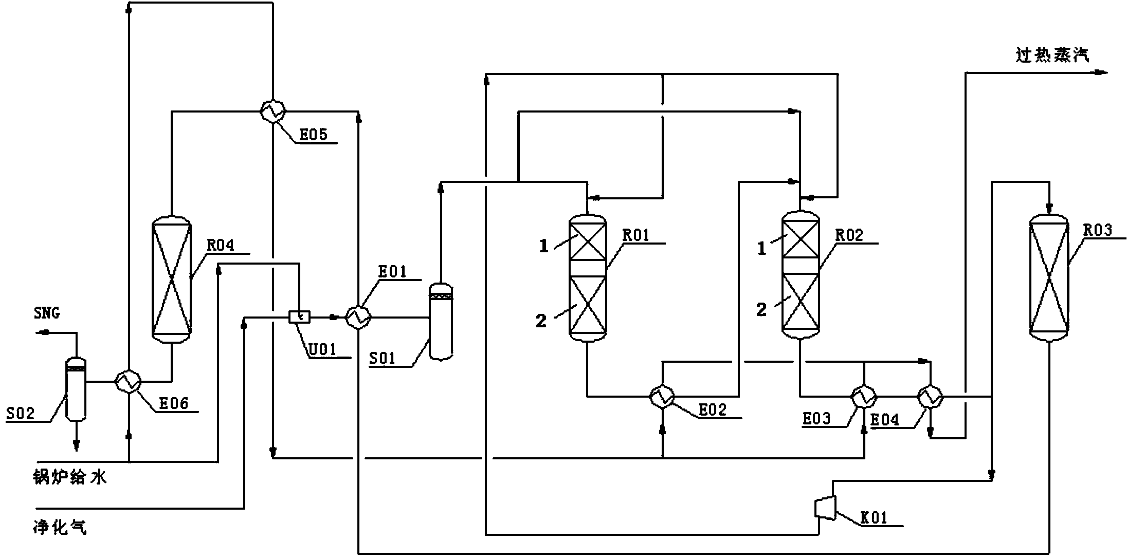
[0033] The ejector U01 passes through the pipeline in turn through the purified gas preheater E01, 1# separator S01, four methane reactors, namely 1# methane reactor R01, 2# methane reactor R02, 3# methane reactor R03, 4# methane Reactor R04, 2# boiler feed water preheating E06, and 2# separator S02 are sequentially connected in series; among the four methane reactors connected in series, the synthesis gas outlet of 1# methane reactor R01 passes through 1# waste pot E02 and The connection of the synthesis gas inlet of 2# methane reactor R02, the synthesis gas outlet of 2# methane reactor R02 is connected with the synthesis gas inlet of 3# methane reactor R03 through 2# waste pot E03, steam superheater E04, the 3 The synthesis gas outlet of #methane reactor R03 is connected to the synthesis gas inlet of 4# methane reactor R03 through purifier preheater E01...


PUM


Abstract

The invention relates to a coal natural gas methanation technology and a system thereof. The problems that in the existing methanation technology, system operation reliability awaits improvement, reaction temperature and reaction balance control is hard, catalyst service life is short, and a metal dust reaction is easy to happen are solved. The coal natural gas methanation technology comprises the steps that purified gas from an upstream purifying device sequentially passes four series-connection methane reactors, a number2 boiler water supply preheater and a number2 separator to obtain synthetic natural gas, the purified gas and boiler supplied water which is supplied at intervals are sprayed by an ejector in a mixed mode, then the temperature of the purified gas rises to 280-350 DEG C through a purified gas preheater, and the purified gas and steam after separation through a number1 separator are mixed and then sent to the four series-connection methane reactors. The technology is simple, device operation and investment cost is low, energy is saved, the environment is protected, and the system is high in operation stability, long in service life of catalysts, and good in heat energy recovery effect.

Description

technical field [0001] The invention relates to a coal-to-natural gas methanation process and a system thereof. Background technique [0002] Coal-to-natural gas technology is that the crude gas produced by coal gasification is adjusted to the appropriate H / CO by CO transformation, and then purified to remove acid gas and other impurities, and the qualified purified gas is generated by methanation to meet the requirements of the national natural gas standard. of synthetic natural gas. [0003] Methanation is a strongly exothermic process, and studies have shown that the adiabatic temperature rise exceeds 70 °C for every 1% CO converted. The methanation reaction of the coal-to-natural gas project has the characteristics of high CO concentration, large heat release, and high reaction temperature, and has high requirements for equipment and pipeline materials. In the methanation process, the control of reaction balance and reaction temperature, as well as the recovery of a la...

Claims


Application Information

Patent Timeline
IPC IPC(8): C10L3/08
Inventor 晏双华卢文新李繁荣胡四斌徐建民夏吴
Owner WUHUAN ENG
Learn More