Hole boring device

A boring and blind hole technology, applied in the direction of boring bars, turning equipment, tool holder accessories, etc., can solve the problems of easy vibration of the tool bar, decline in workpiece quality, chipping, etc., to achieve less vibration, increased strength, and reduced The effect of the broken knife

Inactive Publication Date: 2013-12-18
XUZHOU SILK FIBER TECH
View PDF0 Cites 4 Cited by
  • Summary
  • Abstract
  • Description
  • Claims
  • Application Information

AI Technical Summary

Problems solved by technology

[0002] In the field of mechanical manufacturing technology, holes with larger diameters and higher precision are generally manufactured using boring devices and corresponding processes. The existing boring devices are generally a boring bar installed on a boring machine and a Although the existing boring device h

Method used


Image

  • Hole boring device

Examples


Embodiment Construction

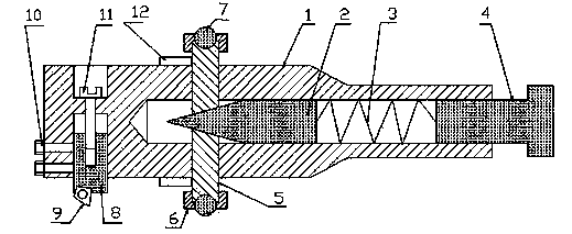
[0010] In the figure, this kind of boring device includes a cutter bar 1, a cone head rod 2, a spring 3, a top wire 4, a support column 5, a flange cap 6, a steel ball 7, a cutter seat 8, a cutter head 9, a bolt 10, an adjustment Screw mandrel 11, spring leaf 12, described a kind of boring device is provided with taper head rod 2 in the middle blind hole inner end of cutter bar 1 afterbody, and the front end of taper head rod 2 is a conical structure, and at cutter bar 1 waist A support column 5 is symmetrically installed on the top of the support column 5. The inner end of the support column 5 is a bevel-shaped structure. Vertical, the upper and lower ends of the support column 5 are respectively fixed with a steel ball 7 through the flange cap 6, and a spring leaf 12 is respectively fixedly installed on the knife bar 1 on the side of the support column 5, and one end of the spring leaf 12 is connected to the support column 5. The outer circle parts of the tool bar 1 are sn...


PUM


Abstract

The invention discloses a hole boring device. A conehead rod is arranged at the inner end inside a middle blind hole positioned at the tail of a knife bar, the front end of the conehead rod is of a cone-shaped structure, supporting pillars are symmetrically installed on the waist of the knife bar, the inner end of every supporting pillar is of an inclined-plane-shaped structure, the inclined plane of every supporting pillar is contacted with the conical surface of the conehead rod, the central axis of every supporting pillar is perpendicular to the central axis of the knife bar, steel balls are fixed at the upper ends and the lower ends of the supporting pillars respectively through flange caps, a top thread is installed on an opening part of the middle blind hole of the knife bar, and a plurality of bolts are arranged at the head of the knife bar and tighten and loosen a knife holder. The hole boring device is not subjected to the influence of eccentric acting force easily in cutting, the knife bar does not vibrate easily, workpiece quality is good, and knife collapse can be reduced simultaneously.

Description

Technical field [0001] The present invention involves a mechanical processing device, which specifically involves a kind of holes, which belongs to the field of mechanical manufacturing technology equipment technology. Background technique [0002] In the field of mechanical manufacturing technology, holes with high diameter and higher accuracy are generally made of pores and corresponding processes. The existing pores are generally installed on a tadpole on the bed and installed on the 镗 镗 镗 镗 镗 镗 镗 镗Although the existing holes device is composed of a knife at the end of the pole end, although the existing holes device has a simple structure, but because the rod is in a suspended state in the work, and the eccentric force generated by the knife head during cutting is cuttingInfluence, the knife rod is not only easy to vibrate, resulting in the quality of the workpiece, and sometimes the phenomenon of collapse. Invention content [0003] The purpose of the present invention is: ...

Claims


Application Information

Patent Timeline
IPC IPC(8): B23B29/02B23B27/16
Inventor 孙德荣
Owner XUZHOU SILK FIBER TECH
Why Eureka
Try Eureka