
Mechanical arm

A technology of manipulators and racks, applied in manipulators, program-controlled manipulators, metal processing equipment, etc., can solve problems such as many defective products, low production efficiency, and hidden safety hazards.

Inactive Publication Date: 2013-12-18
何芳
View PDF5 Cites 6 Cited by
  • Summary
  • Abstract
  • Description
  • Claims
  • Application Information

AI Technical Summary

Problems solved by technology

[0002] In the process of processing objects in the sheet metal stamping industry, it is necessary to continuously transfer the stamped objects among different stamping equipment. The traditional production process and method of the sheet metal stamping industry is that one or two operators operate an open-type machine at the same time. Or a closed punching machine, the operation steps are: firstly divide the raw material to be stamped with a slitting machine, then cut the raw material into the required blank size with a cross-cutting machine, and then put the raw material into the stamping die for stamping processing, and complete After that, the stamped products are manually taken out. The entire production process requires more operators to operate. The production method is backward and the strength of the workers is high. There are great safety hazards in the processing process, and its production efficiency is low. The positioning of the process is all manually operated, and it is difficult to perform accurate positioning, so that there are many unqualified products in the stamped products, and the qualified rate of the products is low.
[0003] Therefore, in the prior art, a manipulator is used to replace the manual method to improve the accuracy and efficiency; but the existing manipulator either has a long stroke, which leads to a long moving time, low efficiency and a large space occupied by the equipment due to the stroke; However, the multi-hand cooperation scheme with complex structure has high cost, and the operation stability and precision are not easy to meet the requirements.

Method used


Image

  • Mechanical arm
  • Mechanical arm
  • Mechanical arm

Examples


Embodiment Construction

[0023] The present invention will be described in further detail below in conjunction with the accompanying drawings and specific embodiments.

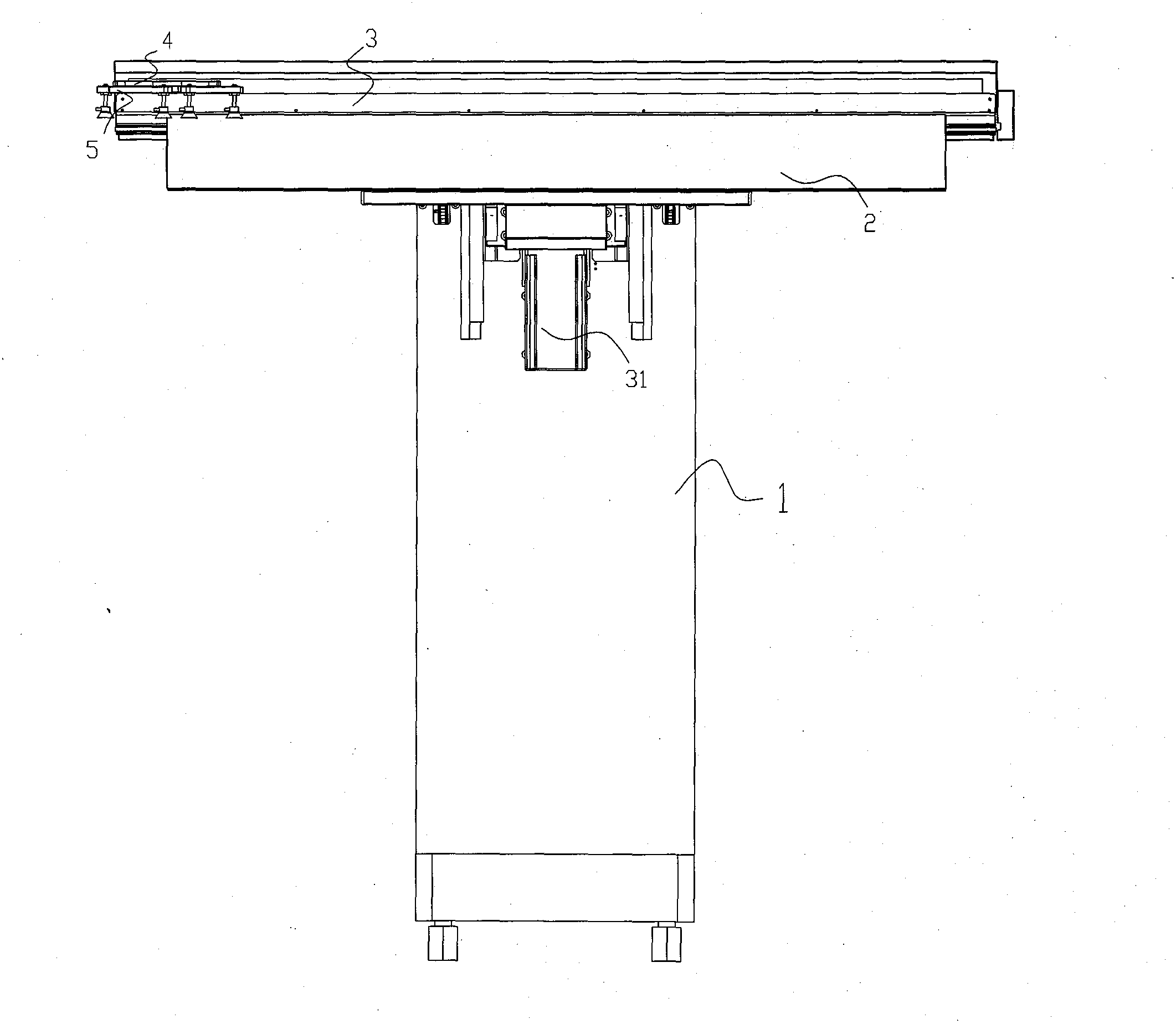
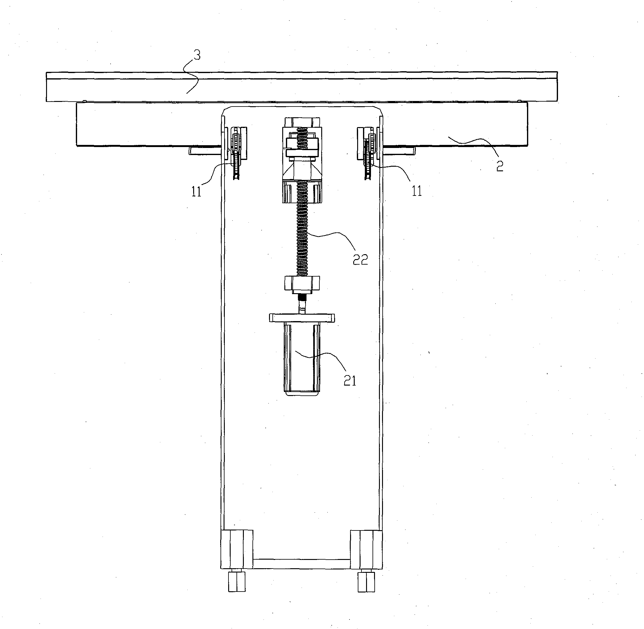
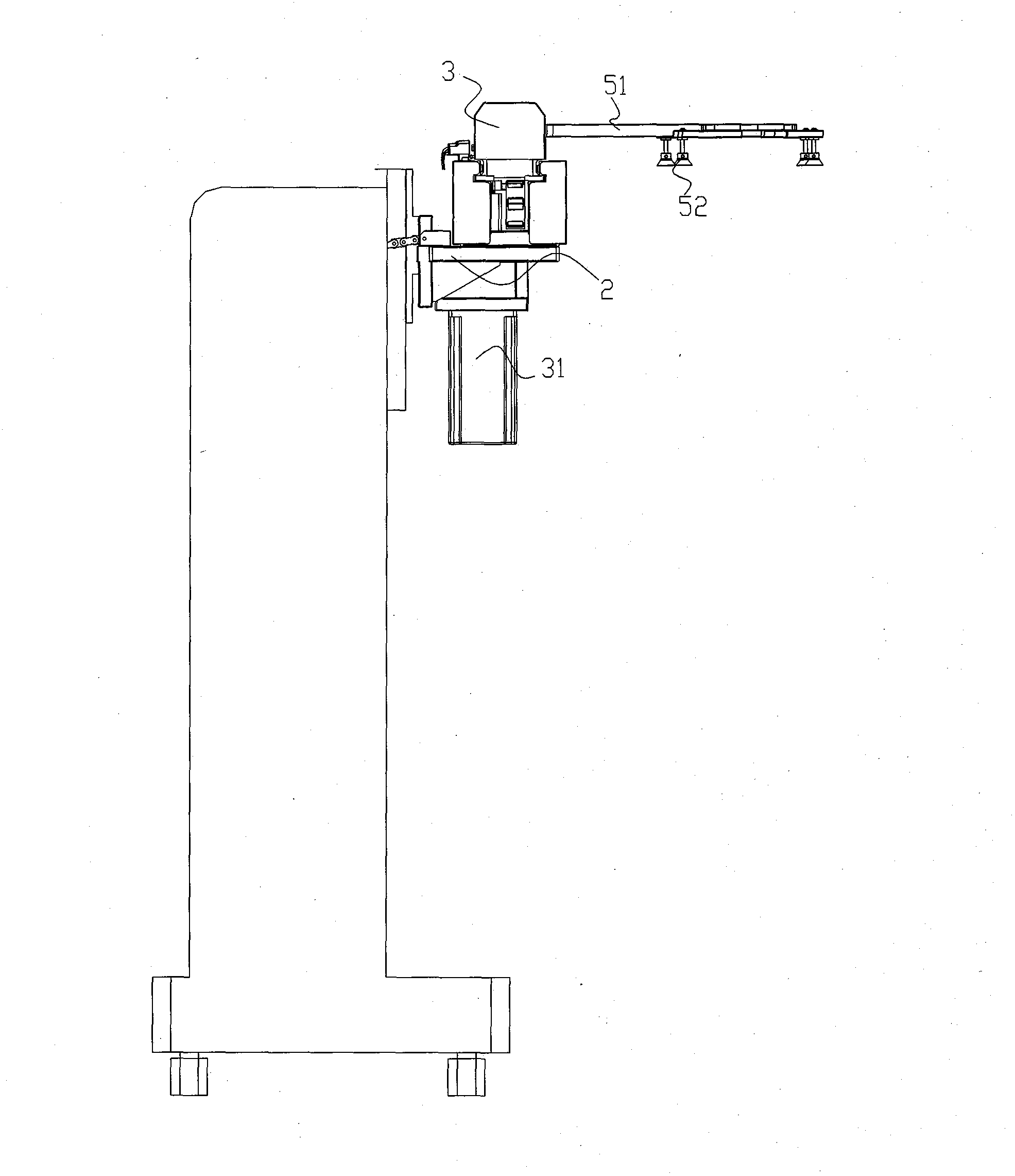
[0024] like figure 1 and 2 As shown, a manipulator according to a specific embodiment of the present invention includes a frame 1 as a base, a Z-axis motion assembly that can move up and down on the frame 1, and a Z-axis motion assembly that can move left and right. The X-axis motion component and the gripper 5 arranged on the X-axis motion component. The manipulator achieves the technical purpose of automatically grabbing and displacing objects through the up, down, left, and right movements of the Z-axis action component and the X-axis action component.

[0025] The Z-axis action assembly in this specific embodiment, figure 2 The display is relatively comprehensive, mainly composed of a Z-axis guide rail, a Z-axis slider 2 mounted on the guide rail and sliding along the guide rail, and a Z-axis servo motor 21 installed on the fr...


PUM


Abstract

The invention discloses a mechanical arm comprising a rack, a Z-axis moving component, an X-axis moving component and a hand grab. The Z-axis moving component is arranged on the rack and can move up and down, the X-axis moving component is arranged on the Z-axis moving component and can move to the left and the right, and the hand grab is arranged on the X-axis moving component comprising a main shaft and an auxiliary shaft. The main shaft can move to the left and the right around the X axis, the auxiliary shaft is assembled on the main shaft and can move to the left and the right on the main shaft along the X axis, and corresponding driving devices are arranged on the Z-axis moving component, the main shaft and the auxiliary shaft. The X-axis moving component is designed to be a double-shaft moving structure with the main shaft and the auxiliary shaft, relative moving speed of a single hand grab on the auxiliary shaft is greatly increased, long-distance X-axis travel equipment space is greatly reduced, the mechanical arm is superior to and can replace a traditional middle material grabbing switching mode, a middle switching procedure is omitted, setup time are saved, and working efficiency and processing accuracy are improved.

Description

technical field [0001] The invention relates to the technical field of mechanical automation, in particular to a manipulator for moving objects, in particular to a manipulator for loading and unloading materials in the sheet metal industry. Background technique [0002] In the process of processing objects in the sheet metal stamping industry, it is necessary to continuously transfer the stamped objects among different stamping equipment. The traditional production process and method of the sheet metal stamping industry is that one or two operators operate an open-type machine at the same time. Or a closed punching machine, the operation steps are: firstly divide the raw material to be stamped with a slitting machine, then cut the raw material into the required blank size with a cross-cutting machine, and then put the raw material into the stamping die for stamping processing, and complete After that, the stamped products are manually taken out. The entire production process...

Claims


Application Information

Patent Timeline
IPC IPC(8): B21D43/10B25J9/00
Inventor 何芳
Owner 何芳
Learn More