Impact tool

a technology of impact tool and hammer, which is applied in the direction of manufacturing tools, portable drilling machines, gearing, etc., can solve the problems of increasing the weight and/or the size of the impact tool, and achieve the effects of improving the efficiency of working and machining accuracy, facilitating a further increase in the impact force, and increasing the movement speed of the hammer

Inactive Publication Date: 2010-11-09
PANASONIC ELECTRIC WORKS CO LTD
View PDF29 Cites 30 Cited by
  • Summary
  • Abstract
  • Description
  • Claims
  • Application Information

AI Technical Summary

Benefits of technology

[0009]Therefore, a primary concern of the present invention is to provide an impact tool having the capability of generating a large impact force, while minimizing the increase in weight and size of the impact tool.
[0011]According to the impact tool of the present invention, since the hammer speed is effectively increased in the direction toward the output shaft by the air pressure and the bias force, it is possible to generate a large impact force without using a high power motor and / or a heavy hammer. The biasing unit of the present invention provides the bias force in the direction of accelerating the hammer toward the output shaft independently from the output of the motor, i.e., without using the output of the motor.
[0012]It is preferred that the hammer is biased in the direction toward the output shaft against the hammer holder by the biasing unit to directly receive the bias force. In this case, it is possible to minimize the loss of the bias force, and efficiently increase the impact force. Alternatively, the biasing unit may be formed in the impact tool such that the hammer indirectly receives the bias force through said hammer holder. In this case, there is an advantage that the biasing unit can be designed at a high degree of freedom in the impact tool.
[0014]It is also preferred that the impact tool of the present invention further comprises a bias force adjusting unit configured to control a magnitude of the bias force provided by the biasing unit. In this case, it is possible to achieve an improvement in working efficiently and machining accuracy by appropriately selecting a magnitude of the impact force.
[0015]In addition, it is preferred that the impact tool further comprises an accelerating unit configured to increase a movement speed of the hammer in a direction away from the output shaft immediately after the impact force is provided to the output shaft. In this case, it is possible to realize a smooth reciprocating motion of the hammer, and consequently facilitate a further increase in the impact force.

Problems solved by technology

However, there is a problem that these proposals lead to an increase in weight and / or size of the impact tool.

Method used


Image

  • Impact tool
  • Impact tool
  • Impact tool

Examples


first embodiment

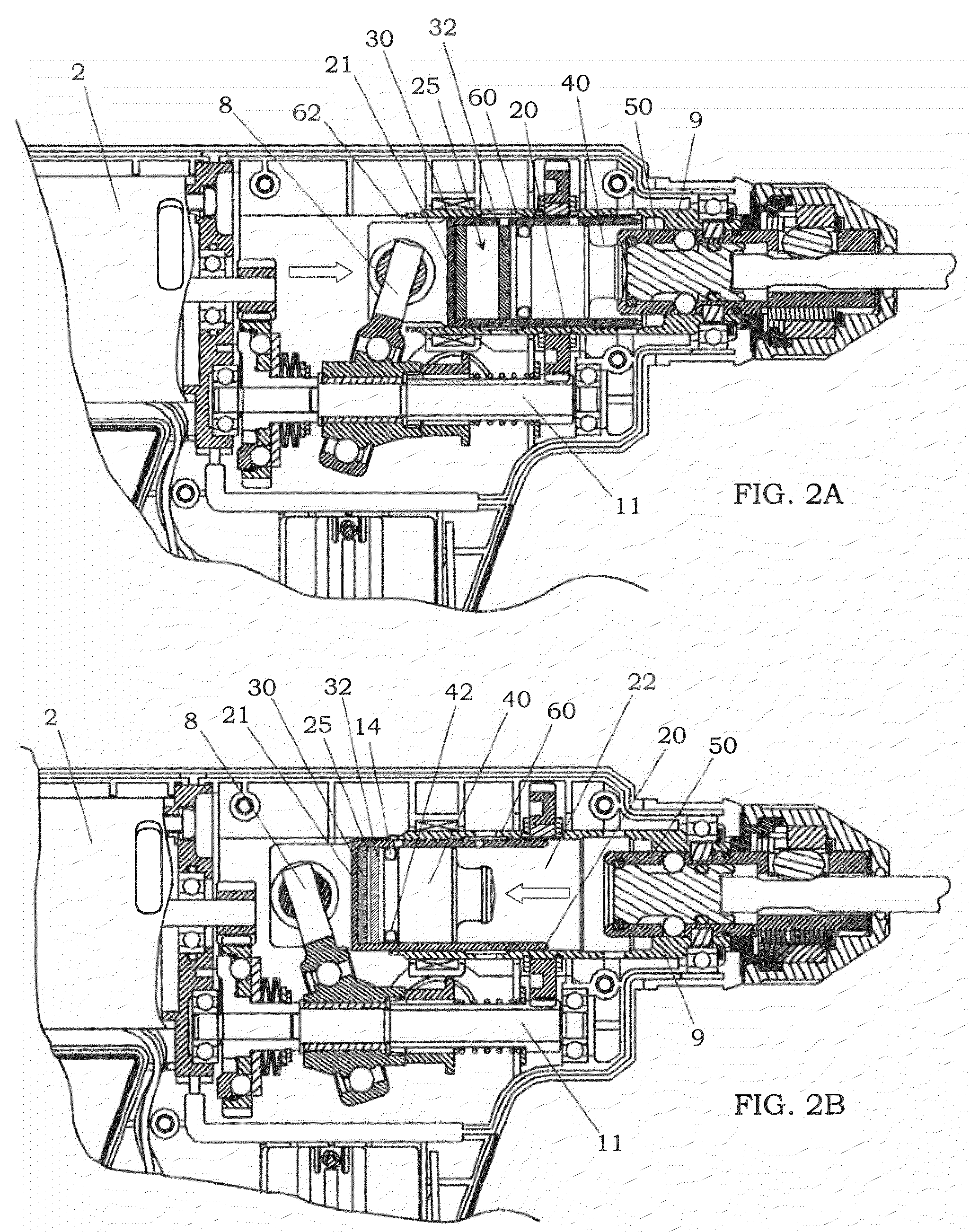
[0026]An impact tool 1 of the present embodiment comprises a motor 2 incorporated in a housing 5, output shaft 50 rotated by the motor, hammer 40 for intermittently providing an impact force to the output shaft, a hammer holder 20 for movably holding the hammer, impact force generating mechanism (8, 12) for converting an output of the motor into a reciprocating motion of the hammer to generate the impact force, air chamber 25 formed between the hammer and the hammer holder such that a volume of the air chamber is variable in response to a position of the hammer relative to the hammer holder; and a biasing unit (30, 32) configured to apply a bias force to the hammer in a direction toward the output shaft. In the embodiments described below, a direction of moving the hammer 40 toward the output shaft 50 is called as “forward” direction, and therefore the “rearward” direction is the direction of moving the hammer 40 away from the output shaft 50.

[0027]An output of the motor 2 is transm...

second embodiment

[0035]An impact tool of this embodiment is substantially the same structure as the first embodiment except that an elastic member is used as a biasing device in place of the magnets. Therefore, the same components are designated by the same reference characters as those of the first embodiment, and duplicate explanation is omitted.

[0036]That is, as shown in FIG. 5, the biasing unit of this embodiment is provided by an elastic member such as coil spring 34, which is disposed in the air chamber 25 defined between the hammer holder 20 and the hammer 40. In this case, when the hammer 40 moves in the rearward direction, the coil spring is compressed in the air chamber 25, so that a restoring force of the coil spring 34 works in the same forward direction as the compression reaction force caused by the volume change in the air chamber. Consequently, it is possible to obtain a further increased impact force, as in the case of the first embodiment.

[0037]In this embodiment, a coil spring hav...

third embodiment

[0038]An impact tool of this embodiment is substantially the same structure as the modification of the first embodiment shown in FIGS. 3A and 3B except for further comprising a bias-force adjusting unit for changing a magnitude of the bias force provided by the biasing unit. Therefore, the same components are designated by the same reference characters as those of the first embodiment, and duplicate explanation is omitted.

[0039]In the present embodiment, the biasing unit is formed with a magnet 32 disposed on a rear end portion of the hammer holder 20, and a magnet 30 disposed in the housing 5 of the impact tool 1 to be in a face-to-face relation with the magnet 32. The magnitude of the magnetic repulsion force developed between those magnets (30, 32) can be controller by operating the bias-force adjusting unit. That is, the magnet 30 is coupled to an adjust lever 70, which is slidably supported in the forward and rearward direction by the housing 5. In addition, the adjust lever 70...


PUM


Abstract

An impact tool for simultaneously providing a rotational force and an impact force to an object has an output shaft rotated by a motor, hammer for intermittently providing an impact force to the output shaft, hammer holder for movably holding the hammer, and an impact force generator for generating the impact force from an output of the motor. An air chamber is formed between the hammer and the hammer holder such that a volume of the air chamber is variable in response to a position of the hammer relative to the hammer holder. In addition, the hammer receives a bias force generated in a direction toward the output shaft by a biasing device. This bias force effectively increases the impact force in cooperation with an air pressure caused by a volume change of the air chamber.

Description

CROSS-REFERENCE TO RELATED APPLICATIONS[0001]This is a divisional of and claims the benefit of priority under 35 U.S.C. §120 from U.S. application Ser. No. 11 / 254,806, filed on Oct. 21, 2005, the entire contents of which are incorporated herein by reference, and which is based upon and claims the benefit of priority from prior Japanese Application No. 2004-311279, filed on Oct. 26, 2005.BACKGROUND OF THE INVENTION[0002]1. Field of the Invention[0003]The present invention relates to an impact tool for simultaneously providing a rotational force and an impact force to an object.[0004]2. Disclosure of the Prior Art[0005]In the past, an impact tool for providing a rotational force of an output shaft to an object, and simultaneously giving an impact force to the object through the output shaft has been used to drill concrete, brick, stone and so on, which is also called as hammer drill.[0006]For example, Japanese Patent Gazette No. 2595262 discloses a hammer drill comprising a motor, out...

Claims


Application Information

Patent Timeline
Patent Type & Authority Patents(United States)
IPC IPC(8): B25D16/00
CPCB25D11/062B25D11/064B25D16/00Y10T74/18056B25D2250/141B25D2250/371
Inventor HASHIMOTO, KOICHITSUBAKIMOTO, HIROYUKIODA, HISASHI
Owner PANASONIC ELECTRIC WORKS CO LTD
Why Eureka
Try Eureka