Multi-channel optical power automatic monitor and testing method thereof

An automatic monitoring and optical power technology, which is applied in the direction of photometry using electric radiation detectors, can solve problems such as blanking of optical power meters, and achieve high stability and precision.

Active Publication Date: 2013-12-11
CHINA ELECTRONICS TECH GRP NO 23 RES INST
View PDF4 Cites 18 Cited by
  • Summary
  • Abstract
  • Description
  • Claims
  • Application Information

AI Technical Summary

Problems solved by technology

This multi-channel optical power meter with automati

Method used


Image

  • Multi-channel optical power automatic monitor and testing method thereof
  • Multi-channel optical power automatic monitor and testing method thereof
  • Multi-channel optical power automatic monitor and testing method thereof

Examples


Embodiment Construction

[0022] The present invention will be described in further detail below in conjunction with the accompanying drawings and embodiments.

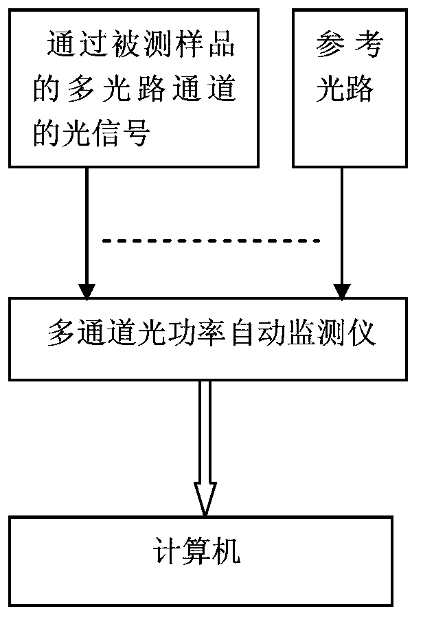
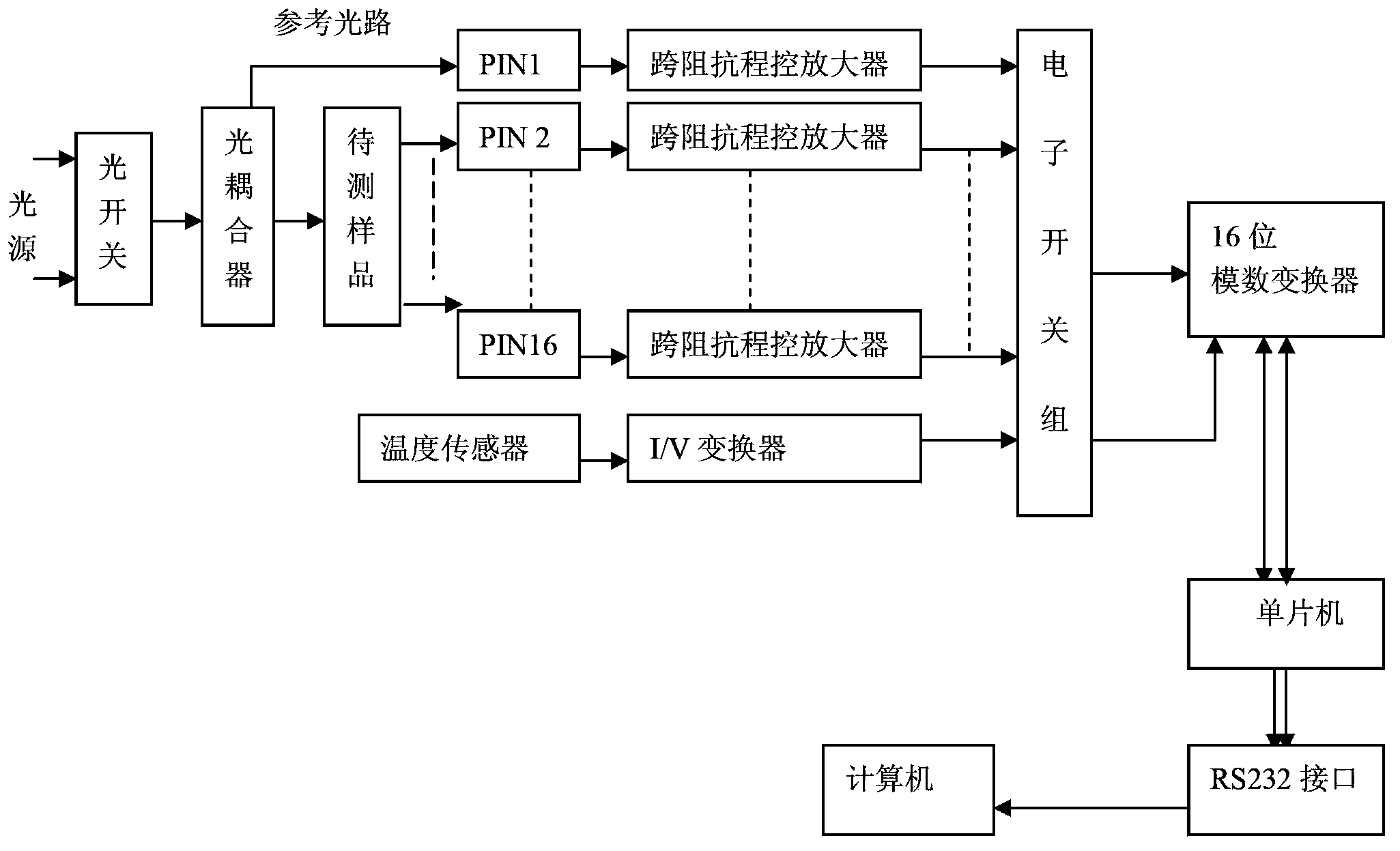
[0023] The multi-channel optical power automatic monitor of the present invention forms a complete test system by adding a laser light source and an optical coupler. The light emitted by the laser light source passes through the optical coupler and is divided into multiple channels of emitted light, one of which is directly connected to the multi-channel optical power automatic monitor. instrument to form a reference path, and the remaining optical path enters the multi-channel optical power automatic monitor through the multi-channel optical channel of the sample under test, and the multi-channel optical power automatic monitor will process the real-time optical power data and single-channel temperature data of multiple channels Send it to the computer through the RS232 interface for subsequent processing, and then display it in real time with...


PUM


Abstract

The invention relates to an optical power testing device used for making up for blanks in the prior art, and provides a multi-channel optical power automatic monitor and a testing method thereof. The multi-channel optical power automatic monitor and the testing method are characterized in that the monitor comprises a multi-channel photodiode, a multi-channel transimpedance program control amplifier, a temperature sensor, an I/V converter, an electronic switch set, an analog-digital converter and a single chip microcomputer. The multi-channel photodiode converts a multi-channel optical signal into a multi-channel current signal, then the multi-channel current signal is converted into a multi-channel voltage signal through the multi-channel transimpedance program control amplifier, the multi-channel voltage signal is input into the analog-digital converter through the electronic switch set to obtain a multi-channel digital signal, and then the single chip microcomputer displays processed real-time optical power data and processed single-channel temperature data of multiple channels through a computer in real time. The monitor and the testing method effectively solve the automatic monitoring problem of mechanical and environment tests of a multi-core optical fiber and a multi-channel branching device, and the stability of a system is better than 0.01dB in a short time and is better than 0.02dB in a long time.

Description

technical field [0001] The present invention relates to optical power testing equipment. technical background [0002] In recent years, with the rapid development of optical fiber communication, optical fiber testing equipment has also developed simultaneously. Optical fiber communication itself is very important to the measurement of transmitted light. The loss of transmitted light directly affects the quality of the optical fiber communication system. Therefore, the accuracy and stability of optical fiber test equipment is particularly important. As a common optical fiber testing equipment, optical power meter is often used to measure the optical power ratio. It can be used to test the transmission loss of optical fiber cables and the insertion loss of optical branch devices when it cooperates with a stabilized laser light source. With the advancement of production technology, the emergence of large-core optical cables and the increase in the number of optical branch devi...

Claims


Application Information

Patent Timeline
IPC IPC(8): G01J1/42
Inventor 袁燕飞陈国庆朱荣华汤钧马磊熊婷婷王莲萍李彦明
Owner CHINA ELECTRONICS TECH GRP NO 23 RES INST
Why Eureka
Try Eureka