
A locking mechanism for a movable mold on a die-casting machine or an injection molding machine

A locking mechanism and injection molding machine technology, applied in the field of injection molding or die-casting, can solve the problems of limiting the scope of application of die-casting machines and injection molding machines, deformation of the clamping surfaces of moving plates and fixed plates, and difficulty in guaranteeing product quality, so as to improve the casting function. and application range, reduce the driving force, improve the quality of the effect

Active Publication Date: 2015-11-25
SDT SMART DIECASTING TECH (SUZHOU) CO
View PDF5 Cites 0 Cited by
  • Summary
  • Abstract
  • Description
  • Claims
  • Application Information

AI Technical Summary

Problems solved by technology

[0004] Since the clamping mechanism restricts the operation of the direct and quick clamping cylinder liner through the split nut to lock the movable mold, it is necessary to set some parts related to the split nut between the movable plate and the pushing mechanism, so that the movable plate There are more parts on the side far away from the mold core, which makes it difficult to install other related components to expand the mold function on this side, which makes the cast product simple and single, which limits the scope of application of the die-casting machine and injection molding machine
At the same time, in order to ensure that the moving plate has a suitable stroke on the frame, a certain distance will be set between the clamping mechanism and the fixed plate to meet the operation of the moving plate. The larger the distance, the pressure generated by the injection will act on the The deformation of the frame rails at both ends of the frame will be greater, and this deformation will cause a small amount of deformation on the joint surface of the moving plate and the fixed plate, which will eventually make it difficult to guarantee the quality of the product

Method used


Image

  • A locking mechanism for a movable mold on a die-casting machine or an injection molding machine
  • A locking mechanism for a movable mold on a die-casting machine or an injection molding machine
  • A locking mechanism for a movable mold on a die-casting machine or an injection molding machine

Examples


Embodiment Construction

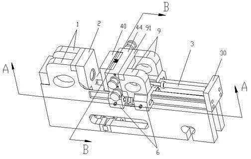
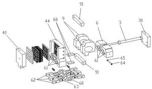
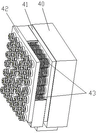
[0034] see Figure 1-2The locking mechanism of the movable mold on the die casting machine or injection molding machine of the present invention has a driving mechanism 3 that pushes the movable template 40 to move closer to or away from the fixed template 2 along the track 11 on the frame 1, and the movable The template 40 is installed on the sliding seat 44 , the ejecting end of the driving mechanism 3 is connected with the sliding seat 44 , and the driving mechanism 3 is fixed on the end of the frame 1 away from the fixed template 2 through the support 30 . The mold locking device 6 is provided below the sliding seat 44, and the mold locking device 6 and the sliding seat 44 are fixedly connected or integrally formed. And molded on the locking cavity 61 on the sliding seat 44, and the locking wedge 63 and the pushing wedge 62 located inside the locking cavity 61, the locking wedge 63 is close to the side wall of the track 11 Set, the pushing wedge 62 is located between the ...


PUM


Abstract

The invention discloses a lock mechanism of a movable mold arranged on a die casting machine or an injection molding machine. The lock mechanism is provided with a driving mechanism for pushing a moving template to move to approach or be far from a fixed template along railways arranged on frameworks, the moving template is installed on a sliding seat, the push-out end of the driving mechanism is connected with the sliding seat, and mode locking devices are arranged below the sliding seat; the mode locking devices comprise mode locking cavities which are respectively positioned on the two sides of the railways and are formed on the sliding seat, and also comprise locking wedge blocks and pushing wedge blocks positioned on the inner sides of the mode locking cavities, and the locking or unblocking of the moving template is realized under the drive of the mode locking driving mechanisms. The lock mechanism provided by the invention has the advantages that the mode locking devices are directly arranged on the sliding seat, the distance from a matched mold position and a mode locking position is very short, the influence of material shooting pressure to framework deformation is greatly reduced, meanwhile, the driving force of the matched mold driving mechanism is reduced, and an energy source and the cost are further saved; one side of the moving template is provided with multiple spaces for installing other function expanding devices, and the application range of the die casting machine or the injection molding machine is enlarged.

Description

technical field [0001] The invention relates to the technical field of injection molding or die-casting, in particular to a mold locking mechanism for a movable mold on a die-casting machine or an injection molding machine. Background technique [0002] When the workpiece is produced by an injection molding machine or a die-casting machine, many workpieces need to be condensed under a certain injection pressure to improve the quality of the product. In order to ensure that the movable mold is fixed relative to the fixed mold during injection molding or die-casting, it is necessary to lock the movable mold. [0003] The traditional locking method mainly locks the fixed mold by locking the connecting rod connecting the movable mold and the pushing mechanism. For example, Chinese patent document CN20296512U discloses a direct pressure mold clamping mechanism for injection molding machines and die-casting machines, including a tail plate with a high-pressure mold clamping oil c...

Claims


Application Information

Patent Timeline
Patent Type & Authority Patents(China)
IPC IPC(8): B29C45/67B22D17/26
Inventor 捷卡姆·查马特
Owner SDT SMART DIECASTING TECH (SUZHOU) CO
Learn More