
Simple flyer sticking and clamping special device and usage thereof

The technology of a special device and flyer is applied in the field of the special device for positioning and clamping the flyer in the laser-driven flyer micro-forming, which can solve the problems of low working efficiency, reduced impact forming effect, and flyer wrinkle, etc. Improve the accuracy of the pasting position, ensure the consistency of pasting, and the effect of uniform bonding force

Inactive Publication Date: 2013-12-11
JIANGSU UNIV
View PDF6 Cites 8 Cited by
  • Summary
  • Abstract
  • Description
  • Claims
  • Application Information

AI Technical Summary

Problems solved by technology

Due to the small size and thin thickness of the flyer, the problem of inaccurate lamination position will occur during the bonding process, and the phenomenon of wrinkling and bending of the flyer will appear, and the work efficiency is not very high.
, it is impossible to control and measure the bonding force between the flyer and K9 glass during the pasting process, the size of the bonding force cannot be guaranteed, and the bonding effect of the same batch of flyers cannot be guaranteed. At the same time, it takes time to prepare for the laser-driven flyer forming experiment
The above problems reduce the impact forming effect to a certain extent, and cannot guarantee the uniformity of each forming effect in the laser-driven flyer forming technology

Method used


Image

  • Simple flyer sticking and clamping special device and usage thereof
  • Simple flyer sticking and clamping special device and usage thereof
  • Simple flyer sticking and clamping special device and usage thereof

Examples


Embodiment Construction

[0023] The details and working conditions of a simple special device for sticking and clamping flyers of the present invention will be described in detail below in conjunction with the accompanying drawings.

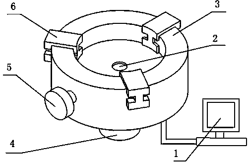
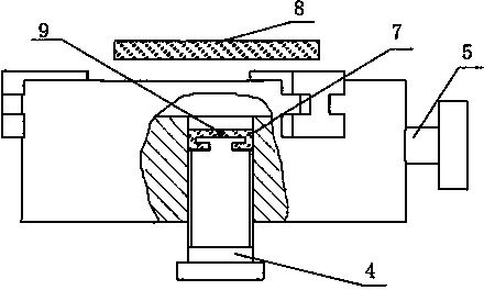
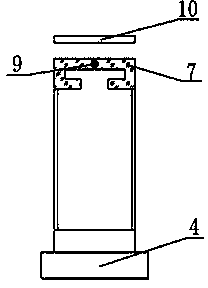
[0024] The structure of a simple flying piece sticking and clamping special device of the present invention is as follows: figure 1 As shown, its working principle is as follows figure 2 As shown, the device is set on a glass tank 3 for placing K9 glass, and a flyer tank 2 with a through-hole structure is arranged in the middle of the glass tank 3 . The device consists of K9 glass fixing system, flyer clamping and positioning system and pressure testing system.

[0025] The K9 glass fixing system includes at least three positioning blocks 6 arranged on the edge of the glass tank 3 (the present invention is only described in the case of three positioning blocks 6 ) and arranged on the outer wall of the glass tank 3 for adjusting the positioning blocks 6 to shrink Or th...


PUM


Abstract

The invention discloses a simple flyer sticking and clamping special device and usage thereof, which belong to the field of laser-driven flyer micro-forming. The device comprises a K9 glass fixing system, a flyer clamping and positioning system and a pressure test system, the K9 glass fixing system comprises positioning blocks and a clamping handle, the positioning blocks are arranged on the brim of a glass trough, the clamping handle is used for adjusting the positioning blocks to contract or expand, the flyer clamping and positioning system comprises a rotary bolt and a protective layer, the rotary bolt is arranged in a flyer socket and used for driving a flyer to move up and down in the flyer socket, the protective layer is fixed on the top of the rotary bolt, the pressure test system comprises a pressure sensor and a pressure display, the pressure sensor is embedded in the protective layer, and the pressure display is connected with the pressure sensor. The accuracy of the sticking position of the flyer is increased, the consumption of working hours is reduced, the uniformity of the adhesion between the flyer and a piece of K9 glass and the sticking uniformity of each flyer target are guaranteed, the accuracy of experiments is increased, and the formability of machining is enhanced to a certain degree.

Description

technical field [0001] The invention relates to a flying piece bonding and clamping device and a method for using the same, in particular to a special device for positioning and clamping the flying pieces in micro-forming of the laser-driven flying pieces and a using method thereof. Background technique [0002] Laser-driven flyer impact forming technology is a new type of micro-component forming technology, that is, the laser-driven flyer replaces the forming process of laser direct impact, and the laser energy is converted into the kinetic energy of the flyer. The collision generates high-pressure shock waves on the collision interface, and the high-pressure shock waves propagate to the inside of the material, and under the constraints of the mold, high-speed deformation occurs. [0003] The flyer used in the laser-driven flyer impact forming technology is an ultra-thin metal sheet punched out of a metal foil, which is bonded to the middle of the K9 glass with an adhesive....

Claims


Application Information

Patent Timeline
Patent Type & Authority Applications(China)
IPC IPC(8): B23K26/42B21D26/06B81C99/00
Inventor 王霄袁耀强沈宗宝顾春兴张强陆萌萌刘会霞
Owner JIANGSU UNIV
Learn More