
A scheduling method, network equipment and terminal equipment

A technology of network equipment and scheduling method, applied in electrical components, wireless communication, etc., can solve problems such as redundancy or shortage of uplink and downlink resources, degradation of user experience, deterioration of system performance, etc., to avoid waste of wireless resources and improve control information efficiency , flexible and changeable frame structure

Active Publication Date: 2018-03-16
BEIJING NUFRONT MOBILE MULTIMEDIA TECH
View PDF9 Cites 0 Cited by
  • Summary
  • Abstract
  • Description
  • Claims
  • Application Information

AI Technical Summary

Problems solved by technology

At this time, although there are services waiting to be transmitted, the air interface resources are not properly used, which will also cause a huge waste of air interface resources
Contention conflict and random backoff are important factors that cause low efficiency of 802.11 system
More importantly, with the increase of the number of terminals, the collision probability index increases, and the system performance will be worse
[0010] (2) Technical disadvantages of TDD LTE Femto
Faced with a wide variety of data services, the asymmetric characteristics of the uplink and downlink services are inconsistent, and this statically configured frame format cannot adapt to the needs of various data services
When the service characteristics change, the initially configured uplink and downlink resources will have certain redundancy or shortage, which will not only cause waste of wireless resources, but also increase service delay
Although wireless resources are allocated for different terminals for uplink and downlink communication through scheduling, its statically configured frame structure cannot flexibly allocate wireless resources for uplink and downlink, and cannot adapt to service changes with a small granularity. When services and resources When the configuration is unbalanced, it may cause long queues, reduce user experience, or cause waste of channel capacity.

Method used


Image

  • A scheduling method, network equipment and terminal equipment
  • A scheduling method, network equipment and terminal equipment
  • A scheduling method, network equipment and terminal equipment

Examples


Embodiment 1

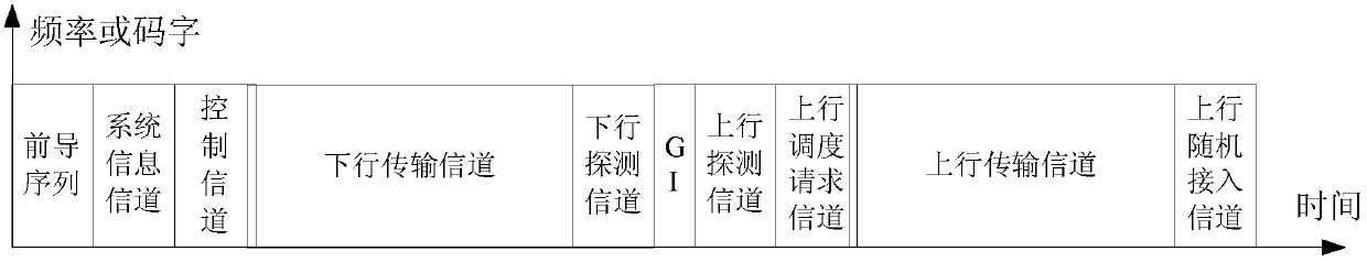
[0077] figure 2A schematic diagram of a frame structure provided by Embodiment 1. Such as figure 2 As shown, the abscissa represents time, and the ordinate represents frequency. Each frame includes a downlink subframe and an uplink subframe, and the downlink subframe and the uplink subframe are divided into different channels according to functions, and each channel is divided into different fields according to functions.

[0078] The downlink subframe is at least divided into a preamble sequence, a system information channel, and a control channel. There is a downlink guard interval DGI and an uplink guard interval UGI between the downlink subframe and the uplink subframe. The downlink guard interval DGI is the guard interval from downlink to uplink transceiving; The interval UGI is the guard interval from uplink to downlink transmission and reception, and the configuration of DGI and UGI is indicated by the periodic broadcast message of the system information channel.

...

Embodiment 2

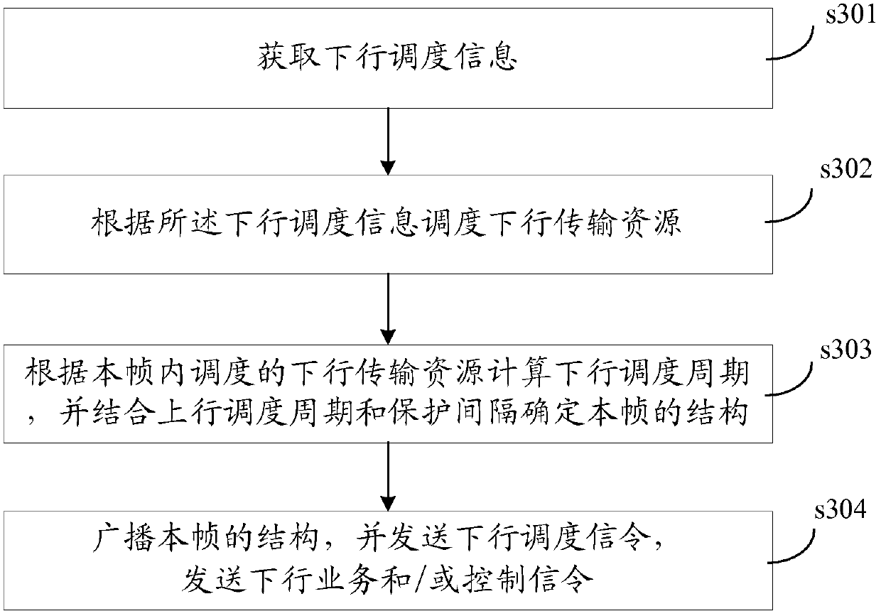
[0115] image 3 It is a schematic flowchart of a scheduling method suitable for downlink scheduling provided by Embodiment 2 of the present invention. The following describes the downlink scheduling and transmission process in detail, including the following four steps:

[0116] Step s301: the network device acquires downlink scheduling information;

[0117] Wherein, the downlink scheduling information includes scheduling requirements of each terminal device or different service flows of each terminal device (for example: services to be scheduled and queue lengths, QoS requirements of different services, service priorities, etc.).

[0118] Among them, step s301 may also include: obtaining the state information or quality information of the downlink transmission channel from the network device to each terminal device (whether the network device can obtain the state information or quality information of the downlink transmission channel depends on the capability of the terminal...

Embodiment 3

[0149] In the third embodiment, the downlink scheduling and transmission process under the condition that the CAP measures the quality of the downlink channel through the uplink detection channel is specifically described, specifically including the following steps:

[0150] Step s401: The CAP obtains downlink scheduling information and the quality of the downlink transmission channel, including: the CAP schedules two uplink sounding channels for the two STAs that need to be scheduled, that is, STA1 and STA2, and schedules one uplink transmission channel for the STA1 that needs to be scheduled, and STA1 and STA2 transmit sounding signals on the uplink sounding channel, the CAP measures the quality of the uplink transmission channel through the uplink sounding signal, and obtains the quality of the downlink transmission channel corresponding to each STA1 and STA2 based on the uplink and downlink reciprocity of the TDD system;

[0151] Step S402: The CAP measures the channel stat...


PUM


Abstract

The invention discloses a scheduling method, network equipment and terminal equipment. The method includes: obtaining scheduling information; scheduling transmission resources according to the scheduling information; calculating uplink scheduling period and downlink scheduling period according to the transmission resources scheduled in this frame; The uplink scheduling period, downlink scheduling period and guard interval determine the structure of this frame; broadcast the structure of this frame, and send scheduling signaling. Through the present invention, different service characteristics and demands are considered for future rich and diverse data services, and a dynamic resource configuration variable frame structure that satisfies both link self-adaptation and service demand self-adaptation is designed. At the same time, the dynamic configuration of the frame structure can meet the processing time requirements of devices with different processing capabilities.

Description

[0001] This application claims that the application date is March 25, 2011, the application number is 201110074598.5, the title of the invention is the adjustment method of the demodulation pilot in the wireless communication system and the priority of the prior application of the system, and the application date is March 2011 On the 31st, the application number is 201110080637.2, and the invention name is a scheduling method, wireless communication system and equipment. The priority of the earlier application of the communication system, and the application date is February 16, 2012, the application number is 201210035784.2, and the title of the invention is a scheduling method, network equipment and terminal equipment. The priority of the earlier application is described in The entire content of the earlier application has been embodied in this application. technical field [0002] The invention belongs to the field of wireless communication, and in particular relates to the...

Claims


Application Information

Patent Timeline
Patent Type & Authority Patents(China)
IPC IPC(8): H04W72/04
Inventor 鲍东山王竞刘慎发曾勇波周玉宝闫志刚王飞飞
Owner BEIJING NUFRONT MOBILE MULTIMEDIA TECH
Learn More