
A Diode-Based Protection Circuit for Connector Breakage of Series Energy Modules

A technology for protecting circuits and connectors, applied in the field of protection of series-connected energy components, can solve the problems of burning out analog front ends, arc discharge, burning out circuits, etc., and achieve the effect of avoiding peak voltage

Active Publication Date: 2018-03-30
HANGZHOU BMSER TECH
View PDF5 Cites 0 Cited by
  • Summary
  • Abstract
  • Description
  • Claims
  • Application Information

AI Technical Summary

Problems solved by technology

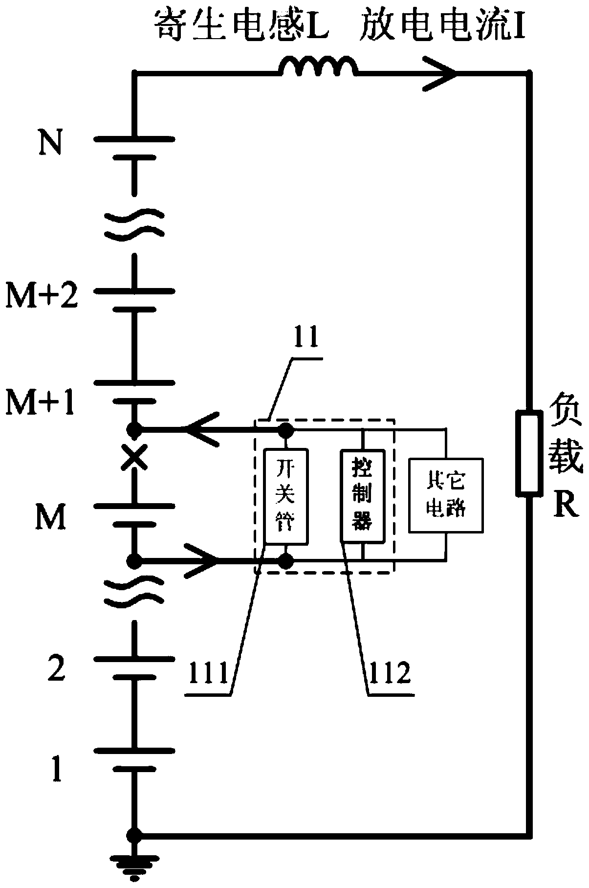
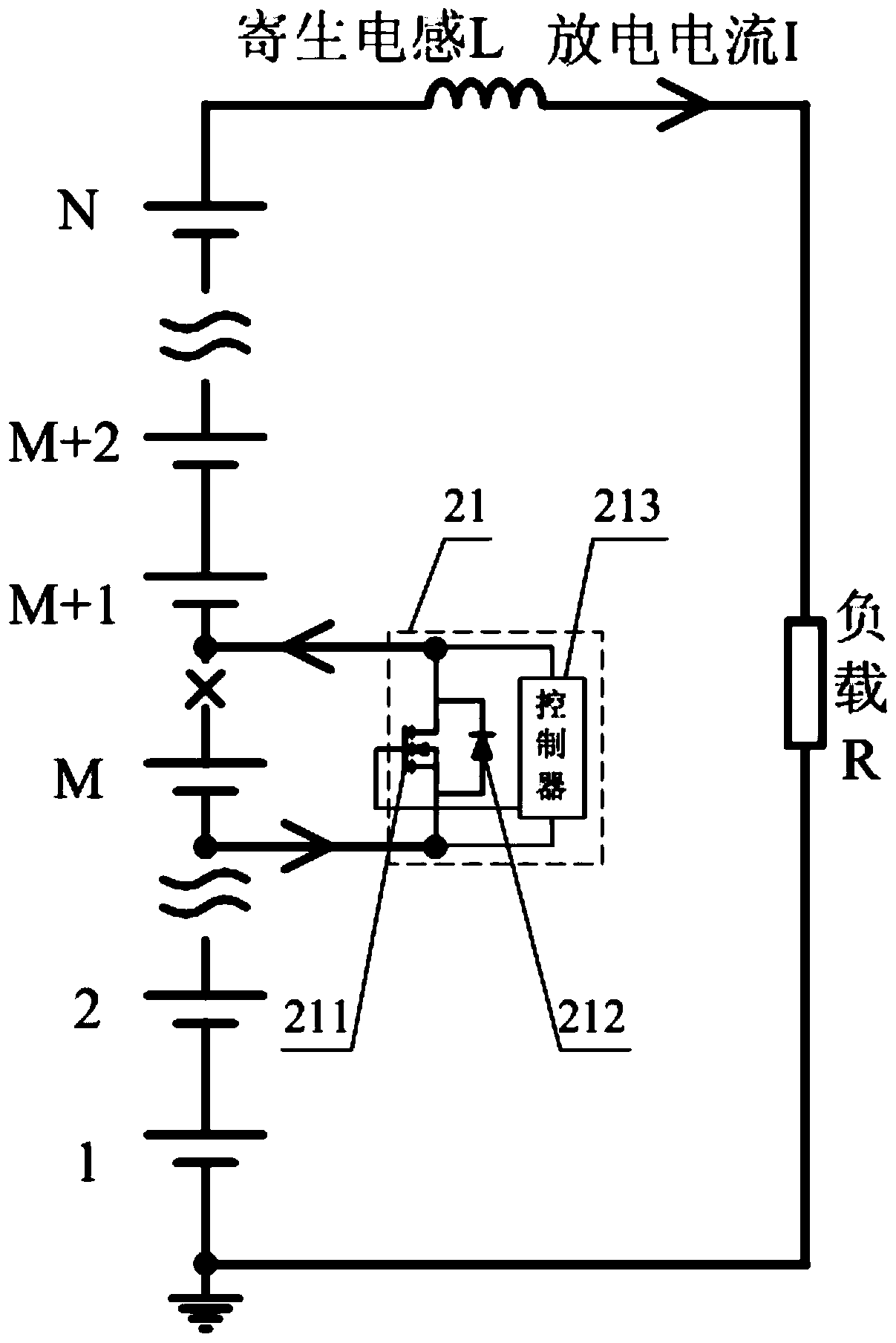
It can be seen that after the connector is disconnected, due to the effect of lead inductance, the loop circuit I cannot drop to zero instantaneously, and this large current forms a freewheeling circuit through the electronic circuit connected to it. The application circuits connected to it are all signal circuits, or low-power circuits, which are not at the same level as the main circuit. These circuits cannot withstand the high current of the main circuit, so they will burn out the circuit
If the impedance of the freewheeling circuit connected to it is large and the current changes suddenly, the voltage changes considerably at this time, and changes from positive voltage to negative voltage, and the withstand voltage range of the analog front end of the supporting circuit of the energy component in series is often slightly larger than The rated voltage of an energy component, and cannot withstand negative voltage, so this voltage is enough to burn out the analog front end
Especially in the occasion of large current, large loop and large lead inductance, serious consequences such as air breakdown and arc discharge are prone to occur
If the energy components in series are in the state of high current discharge and the discharge circuit is suddenly disconnected, due to the effect of the lead inductance, a peak voltage will be generated at the disconnection, which will burn out the circuit connected to it

Method used


Image

  • A Diode-Based Protection Circuit for Connector Breakage of Series Energy Modules
  • A Diode-Based Protection Circuit for Connector Breakage of Series Energy Modules

Examples


Embodiment Construction

[0017] The following will clearly and completely describe the technical solutions in the embodiments of the present invention with reference to the accompanying drawings in the embodiments of the present invention. Obviously, the described embodiments are only some of the embodiments of the present invention, not all of them. Based on the embodiments of the present invention, all other embodiments obtained by persons of ordinary skill in the art without creative efforts fall within the protection scope of the present invention.

[0018] The embodiment of the present invention discloses a diode-based protection circuit for the breakage of the connection part of the series energy component, which can realize the protection of the circuit connected to the series energy component when the connection part of the series energy component breaks.

[0019] like figure 1 As shown, a diode-based series energy assembly connector fracture protection circuit includes: a protection circuit 1...


PUM


Abstract

The invention discloses a diode-based breakage protection circuit for connection parts of series energy components, including: a protection circuit connected to each energy component in the series energy components; wherein: the protection circuit includes: a switch tube and a controller; wherein: The switch tube is connected to the positive and negative poles of the single energy component; the ground of the controller is connected to the negative pole of the single energy component; the power supply of the controller is connected to the positive pole of the single energy component. The invention forms a diode through a controller and a switch tube, and when the connecting parts of the series energy components are broken, it can play the role of continuous flow, avoiding a large current from flowing to the signal circuit or a low-power circuit when the connecting parts of the series energy components are broken, and can play the role of continuous flow. The function of the clamp is to avoid the peak voltage caused by the parasitic inductance when the connection of the series energy component is broken.

Description

technical field [0001] The invention relates to the technical field of protection of series energy components, and more specifically, relates to a diode-based circuit for protection against breakage of connection pieces of series energy components. Background technique [0002] During the power supply process of the series energy components to the load, if any connector is disconnected, the original power supply circuit will be forcibly interrupted. Electronic circuits that are badly connected to this connector, such as analog front ends, etc. For example, assuming that there are N energy components connected in series, and the voltage of a single energy component is V, then the positive terminal voltage of the Mth energy component is normally M*V. When the connection of the Mth energy component is disconnected, the Mth energy The voltage at the positive terminal of the quantity component becomes i*R-L*di / dt-(N-M)*V, where R is the load resistance. It can be seen that afte...

Claims


Application Information

Patent Timeline
Patent Type & Authority Patents(China)
IPC IPC(8): H02H9/04
Inventor 奚淡基周逊伟张云程
Owner HANGZHOU BMSER TECH
Learn More