
High-voltage feed-through, electrical device having a high-voltage feed-through, and method for producing the electrical device

a high-voltage feed-through, high-voltage technology, applied in the direction of transformers/inductance details, electrical apparatus, insulators, etc., can solve the problems of long and heavy high-voltage feed-through designed for high-voltage applications above 500 kv, and avoid the cost of mounting the current sensor

Active Publication Date: 2022-04-05
SIEMENS ENERGY GLOBAL GMBH & CO KG +1
View PDF15 Cites 1 Cited by
  • Summary
  • Abstract
  • Description
  • Claims
  • Application Information

AI Technical Summary

Benefits of technology

This patent describes an improved attachment flange for high-voltage feed-throughs used in electrical devices. The holding part is made up of two parts with outer indentations that form a guide groove, which simplifies the production process. The insulating body is made of a hardened resin, improving its insulating characteristics. The device connection part is attached to the housing with an attachment section and a receiving section made of insulating material, ensuring necessary insulation. A current sensor is also integrated into the current connection line, allowing for quick operation on site without the need for costly mounting procedures.

Problems solved by technology

The movement of the movable part with respect to the holding part is in this case limited to possible production tolerances, to a rotational movement with respect to an axis of the longitudinal axis of the high-voltage feed-through.
As is known, a high-voltage feed-through that is designed for high high-voltage applications above 500 kV is in fact long and heavy.
However, as soon as the high-voltage feed-through is inserted into the corresponding receiving receptacle, the part of the high-voltage feed-through that is inserted into the receiving receptacle may no longer rotate on account of a friction connection between it and the receiving receptacle.

Method used


Image

  • High-voltage feed-through, electrical device having a high-voltage feed-through, and method for producing the electrical device
  • High-voltage feed-through, electrical device having a high-voltage feed-through, and method for producing the electrical device

Examples


Embodiment Construction

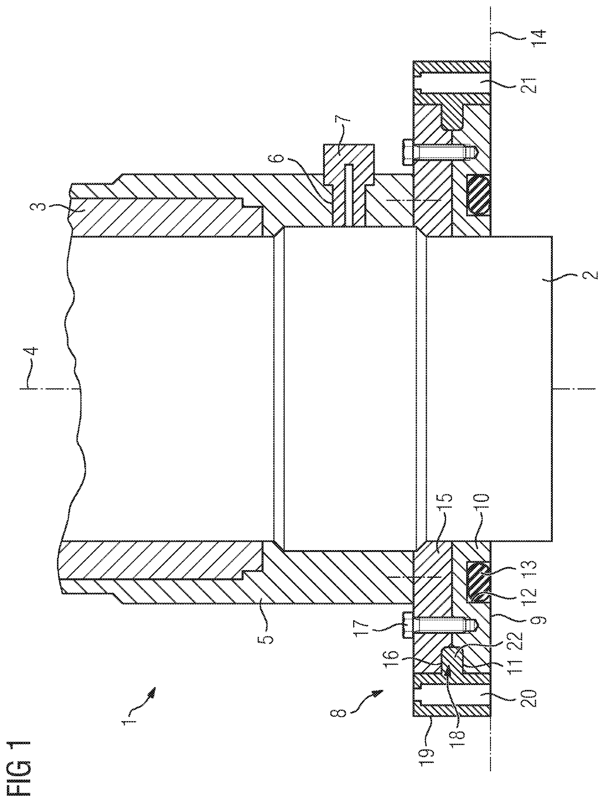
[0030]FIG. 1 illustrates a sectional view of a portion of a high-voltage feed-through 1. The high-voltage feed-through 1 comprises an inner conductor 2. The inner conductor 2 is encompassed by an insulating body 3 that electrically insulates the inner conductor 2 from its environment. The inner conductor 2 extends along a longitudinal axis 4 of the high-voltage feed-through 1. The high-voltage feed-through 1 comprises moreover an outer housing 5 so as to mechanically protect the high-voltage feed-through 1. A potential tap 7 is inserted into a cut-out6 in the housing 5. It is possible by means of the potential tap 7 to monitor a voltage and / or a current at the high-voltage feed-through 1. The potential tap 7 is accordingly configured so as to be connected to a measuring device.

[0031]An attachment flange 8 is provided so as to attach the high-voltage feed-through 1 to a wall 14. The attachment flange 8 extends in an axial manner from the inner conductor 2 outwards, wherein the inner ...


PUM


Abstract

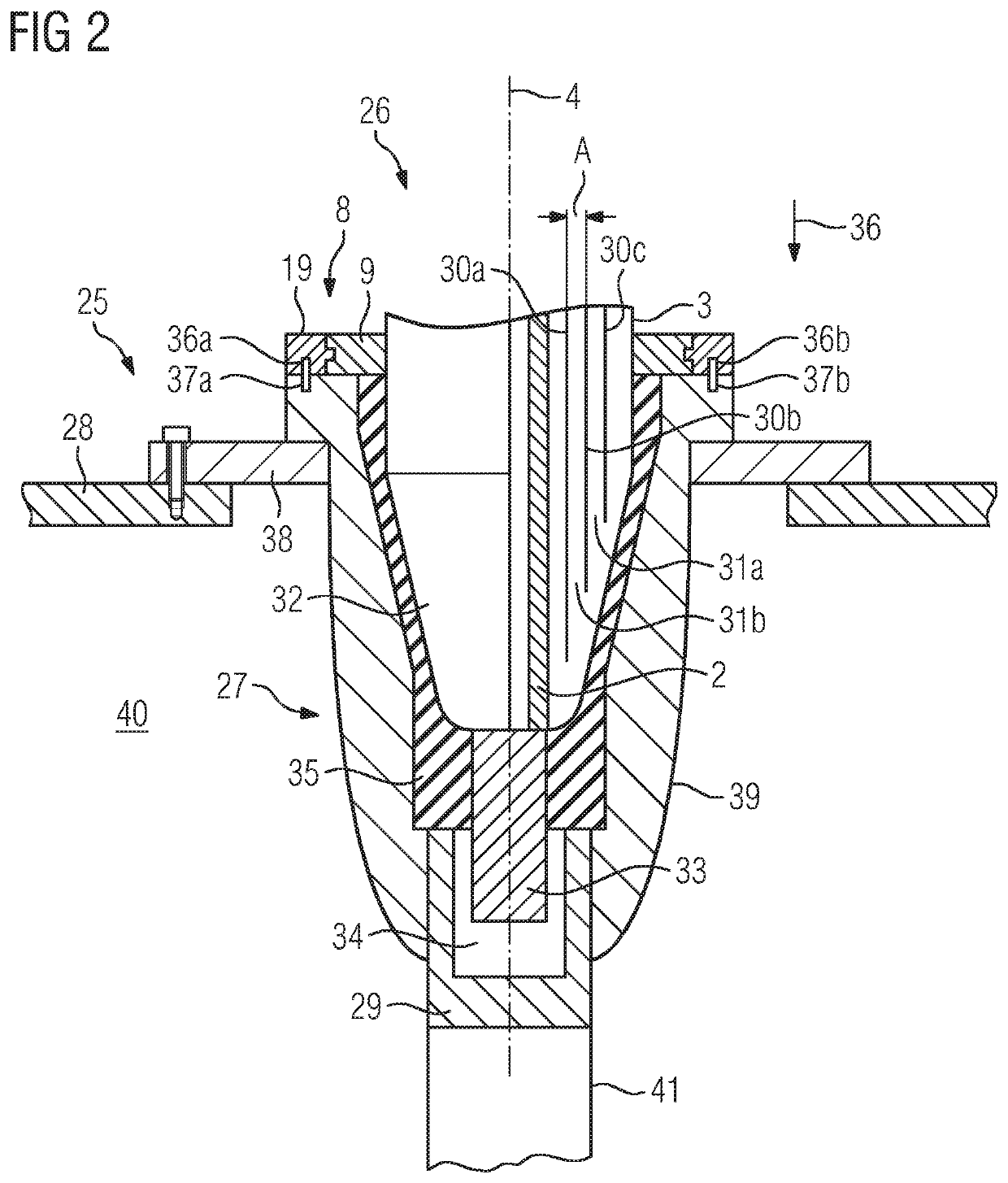
A high-voltage feed-through contains a securing flange for securing the high-voltage feed-through to a wall. The securing flange contains a retaining part and a moving part, wherein the moving part is mounted relative to the retaining part such that it can rotate in relation to a longitudinal direction of the high-voltage feed-through. An electrical device contains a fluid-tight housing and the high-voltage feed-through. A device connection part is provided for receiving and contacting the high-voltage feed-through.

Description

BACKGROUND OF THE INVENTION[0001]Field of the Invention:[0002]The invention relates to a high-voltage feed-through with an attachment flange for attaching the high-voltage feed-through to a wall.[0003]Generally, the object of such a high-voltage feed-through is to insulate a high-voltage line, which is at high-voltage potential and comprises a current-carrying current conductor, from an environment that is essentially at ground potential. In this case, the wall is usually a housing of a high-voltage device or a wall in a high-voltage installation. An inner conductor of the high-voltage feed-through forms a part of the current conductor or is plugged into said current conductor.[0004]A high-voltage feed-through of the type mentioned in the introduction is known from DE 10 2007 022 641 A1. Said document discloses an electrical device in the form of a transformer whose housing comprises a device connection part into which it is possible to plug a high-voltage feed-through so as to conn...

Claims


Application Information

Patent Timeline
IPC IPC(8): H01B17/26H01B17/28H01F27/04
CPCH01B17/265H01B17/28H01F27/04
Inventor ENGELS, ENGELBERTFRIEDEL, THOMASSCHNITZLER, TIMLIDER, PAUL
Owner SIEMENS ENERGY GLOBAL GMBH & CO KG
Learn More