System Architecture For An Active Chassis System On A Motor Vehicle

a chassis system and active technology, applied in the field of system architecture for an active chassis system, can solve the problems of inconvenient operation of vehicle electrical systems, voltage spikes in vehicle electrical systems,

Inactive Publication Date: 2019-01-17
ZF FRIEDRICHSHAFEN AG
View PDF0 Cites 0 Cited by
  • Summary
  • Abstract
  • Description
  • Claims
  • Application Information

AI Technical Summary

Benefits of technology

[0004]Therefore, an object of the present invention is to provide a system architecture that makes it possible to operate a vibration damper with increased power input and power output in an optimal manner while continuing to use the conventional vehicle electrical system for vehicles.
[0008]This allows an energy transfer in both directions, i.e., from the first subsystem to the second subsystem and from the second subsystem to the first subsystem. On the one hand, this makes operation of the active chassis components possible. On the other hand, an energy storage of the vehicle electrical system can be replenished by recovery of energy from the active chassis components. In particular, one or more long-life energy storages which are arranged in the first subsystem and / or in the second subsystem can be replenished. This long-life battery can be, for example, a starter battery or a battery for an electric drive of the vehicle. The first subsystem and the second subsystem are advantageously galvanically decoupled from one another via the voltage converter, particularly via a DC voltage converter. This prevents voltage spikes in the first subsystem resulting from the second subsystem.
[0012]A quantity of satellite control devices provided in the system architecture corresponds to the quantity of active chassis elements. Accordingly, a satellite control device is associated in each instance with an active chassis element. The satellite control devices communicate with the central control device. The central control device coordinates the satellite control devices relative to one another such that the active chassis elements are optimally adapted to external conditions. The central control device can also communicate with other electric elements, for example, a vehicle control device which is arranged in the first subsystem and is operated at the first voltage level. The electric elements can be operated in the first subsystem or in the second subsystem and can be formed, for example, by sensors. To the extent that the electric elements are arranged in different subsystems, in particular between the central control device and the corresponding electric element, a galvanic decoupling is advantageous. This galvanic decoupling can be formed, for example, in the central control device, in the corresponding electric element or discretely. In an advantageous manner, the respective satellite control device is formed in spatial proximity to the associated active chassis element. In particular, it is arranged in or on the electric assembly unit or is integrated therein.
[0019]When using the central control device, it is advantageous, for example, when the measurement values measured by the sensors are conveyed directly to the central control device so that the central control device can ensure optimal cooperation between the satellite control devices. With the exclusive use of satellite control devices inside the second vehicle electrical system, the sensors of the respective active chassis element can communicate directly with the associated satellite control device. The satellite control devices can convey the measurement values measured by the sensors to one another in a corresponding manner via signal lines.

Problems solved by technology

On the other hand, voltage spikes can occur in the vehicle electrical system due to the energy recovery.
The vehicle electrical systems typically used in vehicles are not optimally suited for an operation of this kind.

Method used


Image

  • System Architecture For An Active Chassis System On A Motor Vehicle
  • System Architecture For An Active Chassis System On A Motor Vehicle

Examples


Embodiment Construction

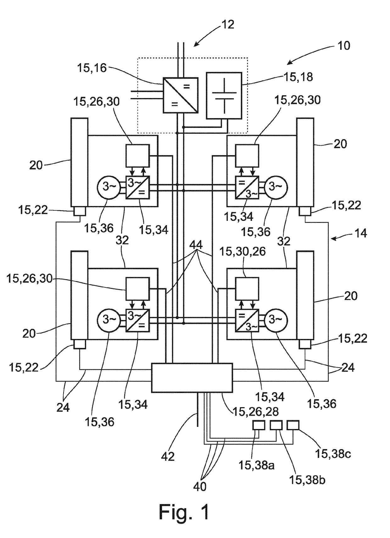
[0029]FIG. 1 shows a vehicle electrical system 10. This vehicle electrical system 10 includes a first subsystem 12 and a second subsystem 14 with corresponding electronics elements 15. The electric subsystem 12 is not shown or described in detail because it can be constructed in accordance with already known vehicle electrical systems 10 with corresponding electronics elements thereof.

[0030]The first subsystem 12 and the second subsystem 14 are connected to one another via a voltage converter 16. This voltage converter 16, which is formed as a DC converter 16, transforms a voltage or voltage level of the first subsystem 12, which is 12 volts in particular, into a second voltage level of the second subsystem 14 which, in this case, is 48 volts in particular. The first voltage level of the first subsystem 12 is accordingly lower than or less than the second voltage level of the second subsystem 14. Further, an intermediate energy storage 18 is arranged at, and is operatively connected...


PUM


Abstract

A system architecture for an active chassis system in a motor vehicle has a vehicle electrical system with a first subsystem and a second subsystem. The first subsystem has a first voltage level that is lower than a second voltage level of the second subsystem (14). At least one electric assembly unit for an active chassis element and at least one control device are provided. The electric assembly unit and the control device are supplied with the second voltage level. A vehicle having a system architecture of this kind is also described.

Description

CROSS REFERENCE TO RELATED APPLICATIONS[0001]This is a U.S. national stage of application No. PCT / EP2016 / 080643, filed on Dec. 12, 2016. Priority is claimed on German Application No. DE102016200403.4, filed Jan. 14, 2016, the content of which is incorporated herein by reference.BACKGROUND OF THE INVENTION1. Field of the Invention[0002]The invention is directed to a system architecture for an active chassis system in a motor vehicle and to a vehicle with a corresponding system architecture.2. Description of Prior Art[0003]A vibration damper for a motor vehicle is disclosed in DE 101 20 102 A1. An electric adjusting mechanism of the damper shown herein is supplied via a vehicle electrical system, wherein externally induced movements of the vibration damper are utilized via the actuator for energy recovery, and this energy is fed back into the vehicle electrical system. On the one hand, dampers of this type must be operated at high power. On the other hand, voltage spikes can occur in ...

Claims


Application Information

Patent Timeline
Patent Type & Authority Applications(United States)
IPC IPC(8): B64G1/22B64G1/10H02J1/00
CPCB64G1/22B64G2001/228H02J1/00B64G1/10B60G17/0157B60R16/03B60G2202/42B64G1/228
Inventor FUSSL, ANDREASHEGEDUS-BITE, ISTVANWOLF, DANIEL
Owner ZF FRIEDRICHSHAFEN AG
Why Eureka
Try Eureka