
cmos wafer automatic test straight pin automatic test socket

A technology of automatic testing and test base, applied in the direction of single semiconductor device testing, etc., can solve the problems of increased testing cost, complicated operation, low service life of probes, etc., to achieve simple testing, simple mechanical structure, and simple and easy testing operation. row effect

Active Publication Date: 2016-04-27
SUZHOU CHUANGRUI MACHINERY & ELECTRICAL TECH
View PDF3 Cites 1 Cited by
  • Summary
  • Abstract
  • Description
  • Claims
  • Application Information

AI Technical Summary

Problems solved by technology

[0005] At the same time, the existing wafer probe test card is generally suitable when the chip PITCH is relatively large, but as the chip PITCH becomes smaller and smaller, it can no longer meet the test requirements
Moreover, the service life of the probes is relatively low, generally only up to about 50,000 chip tests, and the operation of replacing the probes is extremely complicated, which greatly increases the test cost
[0006] In addition, in terms of test circuit board requirements, due to the circuit requirements of the existing wafer probe card itself, the circuit is extremely complex, and the circuit boards generally have more than 10 layers, which puts forward high requirements for the design and processing of circuit boards. Very limited

Method used


Image

  • cmos wafer automatic test straight pin automatic test socket
  • cmos wafer automatic test straight pin automatic test socket
  • cmos wafer automatic test straight pin automatic test socket

Examples


Embodiment Construction

[0030] The technical solution of the present invention will be further described below in conjunction with the accompanying drawings and a preferred embodiment.

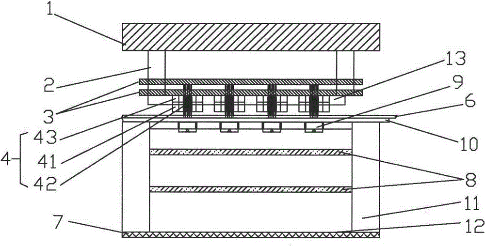
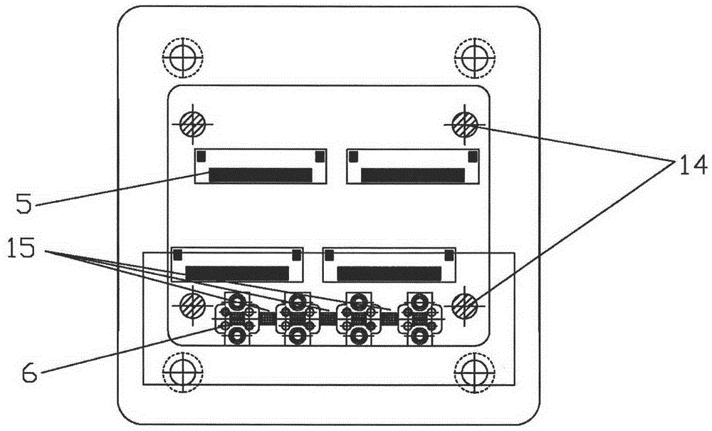
[0031] refer to Figure 1-Figure 7 , a kind of CMOS wafer automatic test straight pin automatic test socket involved in the present embodiment comprises the light box (not shown in the figure) and test base that cooperate with each other, wherein,

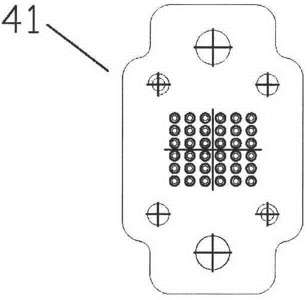
[0032] The base includes a PCB adapter board 3, a test unit 4 and a test lens 9 distributed sequentially from top to bottom, a light box mainly composed of a light source is arranged in front of the test lens, and the test unit includes a plurality of test probes 42 And the probe holding body 41, the probe holding plate 43 and the probe holding frame 13 in order to install the test probe, and, when testing, the wafer to be tested is arranged between the test lens and the test unit, and the test lens and the test unit A contrast image 12 is also provided between the light...


PUM


Abstract

The invention discloses an automatic test socket for a CMOS wafer automatic test straight needle. The automatic test socket for the CMOS wafer automatic test straight needle comprises a light box and a test base, wherein the light box and the test base are mutually matched; the test base comprises a PCB pinboard, a test unit and a test lens, wherein the PCB pinboard, the test unit and the test lens are arranged in sequence from top to bottom; the light box which is mainly composed of a light source is arranged in front of the test lens; the test unit comprises a plurality of test probes, a probe holding body, a probe holding plate and a probe holding frame, wherein the probe holding body, the probe holding plate and the probe holding frame are used for installing the test probes; moreover, at the time of testing, a wafer to be tested is arranged between the test lens and the test unit, and a contrast image is arranged between the test lens and the light source. The automatic test socket for the CMOS wafer automatic test straight needle realizes automatic testing of the CMOS wafer, also enables a CMOS wafer test to be simplified, and is simple and practicable in test operation, simple in mechanical structure, and suitable for testing wafers with various specifications.

Description

technical field [0001] The invention relates to a CMOS wafer test device, in particular to a CMOS wafer automatic test straight pin automatic test socket. Background technique [0002] CMOS wafers are photosensitive chip devices formed by processing photosensitive integrated circuits on silicon wafers, which are widely used in mobile phones, computers, camera devices and other equipment. Generally speaking, CMOS wafers have the characteristics of high product circuit integration and small step distance (about 0.2mm) between solder balls used for circuit derivation. [0003] At present, in the production process of CMOS chips, after the chip is cut from the wafer, manual or automatic testing is performed on a single chip to check the conformity of the chip design and processing. [0004] Existing wafer testing methods are mainly carried out with the help of Wafer Probe Cards, which mainly include two types of oblique needles and straight needles. They are mainly used in non-...

Claims


Application Information

Patent Timeline
Patent Type & Authority Patents(China)
IPC IPC(8): G01R31/26
Inventor 朱小刚柳慧敏
Owner SUZHOU CHUANGRUI MACHINERY & ELECTRICAL TECH
Learn More