Composite material chimney connection joint and method

A technology of composite materials and connecting nodes, which is applied in the direction of combustion methods, combustion product treatment, exhaust gas devices, etc., can solve the problems of heavy field work workload, cracking and damage of flanges, poor ability to eliminate stress, etc., and achieve reduction of direct Contact area, reduce anti-corrosion cost, improve the overall effect

Active Publication Date: 2013-12-04
SOUTHEAST UNIV +1
View PDF5 Cites 0 Cited by
  • Summary
  • Abstract
  • Description
  • Claims
  • Application Information

AI Technical Summary

Problems solved by technology

Composite material flange connection has the advantages of convenient installation and reducing the amount of high-altitude operations; however, composite material flanges are all laminated with molds, which are brittle materials, and the ability to eliminate stress is poor, and stress concentration at the root of the flange is easy to cause cracking and damage , many composite material flanges will partially crack when the high-strength bolts are pre-tightened, and the bolts cannot be pre-tightened as much as possible like steel flanges to ensure the sealing of the interface without damaging the flange; in addition, the flange There are bolt holes on the top, and the bolt holes need to be connected during installation, which increases the number of high-altitude turnover and hoisting
The taper socket connection also has the advantages of convenient installation and reduced overhead work; however, the requirements for the fixing and guiding support of the chimney support are relatively high, and each chimney has at least one fixed support, and this kind of connection cannot well complete the external interface connection
Compared with the other two traditional connection forms, hand lay-up butt jointing is simple in construction, has more overlapping areas, and has better joint strength, so it is the most used connection method; Difficult to operate, need to set up a special construction platform

Method used


Image

  • Composite material chimney connection joint and method
  • Composite material chimney connection joint and method
  • Composite material chimney connection joint and method

Examples


Embodiment 1

[0055] see figure 1 , figure 2 , image 3 , Figure 4 , Figure 5 , Figure 6 , Figure 7 , Figure 8 and Figure 9 Shown:

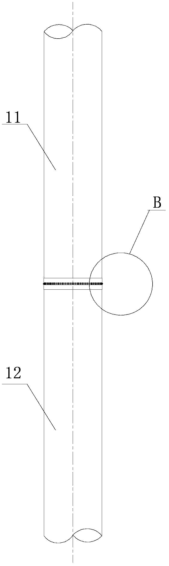
[0056] First, use a grinder to grind off the non-slip coating in the node connection area of ​​the first cylinder 11 and the second cylinder 12 of the composite material chimney. When grinding, care should be taken to control the grinding depth, preferably 0.5mm±0.1mm;

[0057] Next, calibrate the size of the nodes on the first cylinder 11 and the second cylinder 12, and apply epoxy glue on the node connection between the first cylinder 11 and the second cylinder 12, with a thickness of 0.5mm±0.1mm appropriate;

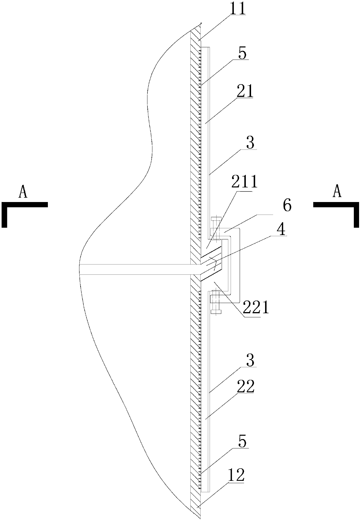
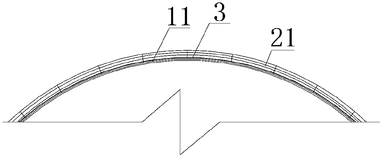
[0058] Next, place the first arc-shaped stabbing plate 21 on the outer surface of the node connection area of ​​the first cylinder 11, the first connecting portion 211 is close to the connecting end of the first cylinder 11, and the barbed spine of the first arc-shaped stabbing plate 21 Facing the first cylinder body 11, press the tho...


PUM


Abstract

The invention discloses a composite material chimney connection joint which comprises a first arc-shaped prickly plate, a second arc-shaped prickly plate, an epoxy resin adhesive layer, a composite material fiber cloth layer and a C-shaped clamp. The invention further discloses a composite material chimney connection method. The composite material chimney connection joint and the composite material chimney connection method have the advantages that the arc-shaped prickly plates are firmly connected with a composite material chimney cylindrical body in an anchoring mode through steel thorns and epoxy resin adhesives, therefore, enough joint strength can be provided for the structure, a joint area is not a weak part of the structure any more, and besides, a composite material chimney can be gradually used as an independent structure beneficially; the scattered arc-shaped prickly plates are tightly wrapped together by the composite material fiber cloth wound on the periphery, and therefore integrality of the structure is improved; the situation that the thorns are pulled out when the arc-shaped prickly plates are stressed is avoided, and therefore the strength of the joint is further improved; the direct contact area between the arc-shaped prickly plates and the outside is reduced, and therefore the cost for corrosion prevention of the arc-shaped prickly plates is lowered.

Description

technical field [0001] The invention belongs to the technical field of heavy anticorrosion, and relates to a composite material chimney connection node and a method, which are used for the connection of composite material chimneys in industries such as thermal power plants and metallurgy. Background technique [0002] In order to reduce the emission of sulfur dioxide and obtain clean electric energy, domestic and foreign power companies generally adopt flue gas desulfurization technology. Among them, limestone-gypsum wet desulfurization without flue gas heat exchanger (GGH) is still the current dominant process scheme. The resulting flue gas has a temperature of about 50° and a high moisture content, which is called wet flue gas. The wet flue gas condenses in the chimney to form condensed acid, which greatly enhances the corrosion of the chimney, which makes people put forward higher requirements for the structure of the chimney and the anti-corrosion performance of the lin...

Claims


Application Information

Patent Timeline
IPC IPC(8): F23J13/04
Inventor 吴刚张保龙刘欣良蒋剑彪
Owner SOUTHEAST UNIV
Why Eureka
Try Eureka