Bead feeding air cylinder of bead nailing machine

A beading machine and cylinder technology, which is used in textile decoration, textiles and papermaking, clothing, etc., can solve the problems of inability to enter the card slot, standby, and nails stuck.

Inactive Publication Date: 2013-12-04
林尧宇
View PDF4 Cites 0 Cited by
  • Summary
  • Abstract
  • Description
  • Claims
  • Application Information

AI Technical Summary

Problems solved by technology

Since the button is pushed forward by the rear cylinder in the slot of the transfer block, the precision requirements for the button, transfer block, slot, rear cylinder and delivery trough are relatively high. If one of the five does not meet the requirements, It will cause the damage of the button or the button cannot enter the card slot. With each push and impact of the rear cylinder, the button will either be stuck in the conveying groove, and the subsequent button operation cannot be performed, or no button will enter the card slot. Empty delivery of the conveying block will make the buttons and beads unable to be riveted and fixed together, or the buttons cannot reach the punching hole of the button cylinder to stand by, or often cause the nails of the buttons to fail to ensure that each foot is not defective , not deformed, the standard fits with the upper bead to complete the punching riveting work, therefore, it will cause the button to be stuck during the beading process, which will bring inconvenience to the beading operation
[0006] At present, due to the high precision of the bead feeding cylinder in the beading operation, if the stroke of the bead feeding cylinder is not accurate, the beading will be weak or the beads will be damaged
The structure of the cylinder of the existing beading machine does not meet the requirements, and the stroke cannot meet the conditions of beading, which needs to be improved

Method used


Image

  • Bead feeding air cylinder of bead nailing machine
  • Bead feeding air cylinder of bead nailing machine
  • Bead feeding air cylinder of bead nailing machine

Examples


Embodiment Construction

[0027] In order for those skilled in the art to better understand the technical solutions provided by the present invention, the following will be described in conjunction with specific embodiments.

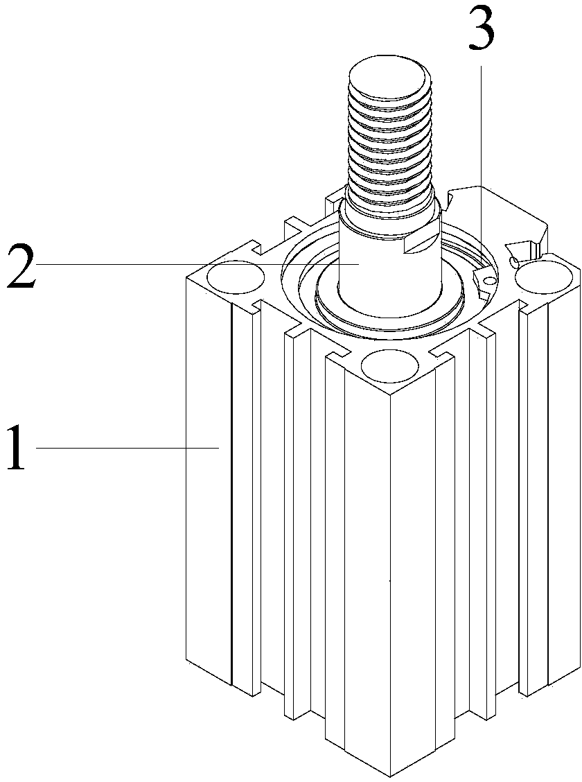
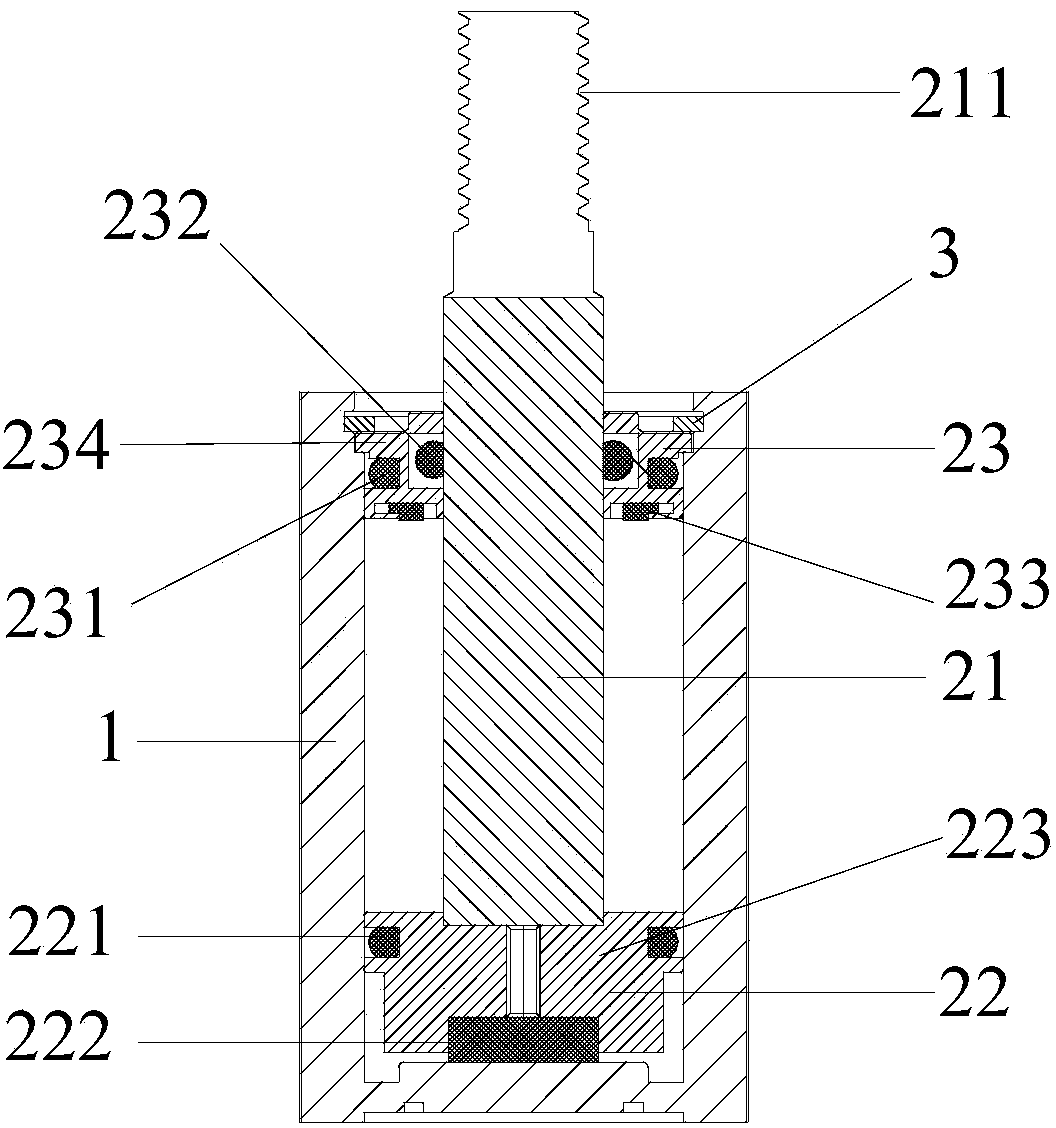
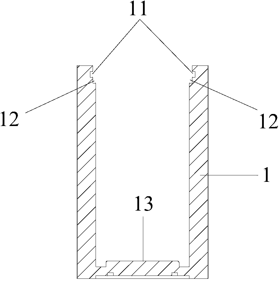
[0028] See Figure 1-Figure 6 , figure 1 It is a schematic diagram of the overall structure of the bead delivery cylinder of the bead nailing machine in the embodiment of the present invention; figure 2 It is a sectional structure diagram of the bead delivery cylinder of the bead nailing machine in the embodiment of the present invention; image 3 It is a cross-sectional structure diagram of the outer cylinder of the bead delivery cylinder of the bead nailing machine in the embodiment of the present invention; Figure 4 It is an exploded structure diagram of the bead delivery cylinder of the bead nailing machine in the embodiment of the present invention; Figure 5 It is a structural diagram of the main shaft and piston in the bead delivery cylinder of the bead nailing machin...


PUM

PropertyMeasurementUnit
Total lengthaaaaaaaaaa
Thicknessaaaaaaaaaa
Thicknessaaaaaaaaaa

Abstract

The invention discloses a bead feeding air cylinder of a bead nailing machine. The bead feeding air cylinder of the bead nailing machine comprises an outer barrel and an air cylinder shaft, wherein the air cylinder shaft comprises a main shaft body, a piston and a sealing opening plate. The piston is connected to the bottom end of the main shaft body, a thread for being connected with a bead blunt pin is arranged at the top end of the main shaft body, the sealing opening plate enters from the top end of the main shaft body and is in sleeved connection to the main shaft body, the air cylinder shaft is inserted into the outer barrel, a clamping position table body and a clamping position groove are formed in the inner side wall of the outer barrel, the clamping position table body limits at the bottom of the sealing opening plate, the clamping position groove is matched with a clamping spring to limit the top of the sealing opening plate, and the effective stroke of the air cylinder shaft is 40mm. Compared with the prior art, the bead feeding air cylinder of the bead nailing machine has the advantages that the structure of an existing air cylinder is improved, and the effective stroke of the air cylinder is precise to be 40mm.

Description

technical field [0001] The invention relates to the field of bead nailing machines, in particular to a bead feeding cylinder of a bead nailing machine. Background technique [0002] Nowadays, with the development of the clothing industry, people are increasingly pursuing the beauty and diversity of clothing. In addition to the requirements for the style of clothing itself, there are also requirements for accessories attached to clothing, so it is necessary to bind some on the clothing. Accessories such as diamonds, beads or plastic hardware buttons can enhance the taste and added value of clothing. In the present application, clothing has a broad meaning and is not limited to clothes and trousers, but also includes footwear, hats, gloves, handbags, and the like. [0003] At first, the original beading operation was done by manual threading, which was very inefficient. Later, the beading machine was developed slowly, and it was changed to mechanized beading. Bead nailing ma...

Claims


Application Information

Patent Timeline
IPC IPC(8): D06Q1/10A41D27/08
Inventor 林尧宇
Owner 林尧宇
Why Eureka
Try Eureka