Uniform flow plate for crystalline silicon diffusion and its crystalline silicon diffusion process furnace
A diffusion process and flow plate technology, applied in crystal growth, diffusion/doping, post-processing, etc., to reduce replacement cost and maintenance time, improve airflow uniformity, and reduce abnormal sheet resistance.
- Summary
- Abstract
- Description
- Claims
- Application Information
AI Technical Summary
Problems solved by technology
Method used
Image
Examples
Embodiment 1
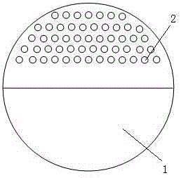
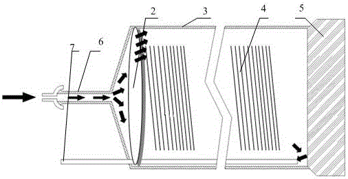
[0032] Such as figure 1 and image 3 shown.
[0033] The uniform flow plate used for the diffusion of crystalline silicon is characterized in that it includes a uniform flow plate body 1, and the uniform flow plate body 1 is divided into a furnace top plate area and a furnace bottom plate area according to the area, and a number of uniform flow holes 2 are opened in the furnace top plate area. The furnace floor area is a sealed plate body.
[0034] The realization principle is: use the uniform flow plate instead of the uniform flow pipe, and set the uniform flow hole 2 for diversion on the uniform flow plate body 1, and the uniform flow hole 2 is only located in the furnace roof area, that is, the uniform flow plate body 1 is installed into the process furnace After inside the body 3, the uniform flow hole 2 is located in the upper area of the furnace body 3 of the process furnace, which can cause the process gas to rise after passing through the uniform flow hole 2, so th...
Embodiment 2
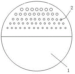
[0046] Such as figure 2 shown.
[0047] The difference between this embodiment and Embodiment 1 is that the size of the uniform flow holes 2 changes from large to small from the furnace roof area to the furnace floor area, and the uniform flow holes 2 of the same height are uniformly distributed in the furnace roof area.
[0048] In the above embodiments, the size of the uniform flow hole 2 is not uniform, and the closer to the top of the furnace body 3 of the process furnace, the larger the hole is. It is preferred to change in a ratio of 10%, that is, the size ratio between the adjacent uniform flow holes 2 in the direction from the top of the process furnace body 3 to the bottom of the process furnace body 3 is 10%.
Embodiment 3
[0050] This embodiment is based on Embodiment 1 and Embodiment 2: the hole axis of the uniform flow hole 2 and the axis of the process furnace body 3 form an included angle of 30°-80°. The uniform flow hole 2 rises and points to the top of the furnace body 3 of the process furnace. This can further cause the airflow to rise. Preferably, the data between 80 degrees and 60 degrees or between 80 degrees and 60 degrees is used for experiments.
[0051] The arrows in the figure indicate the flow direction of the process gas.
[0052] Data description: such as Figure 4 and Figure 5 as shown, Figure 4 Among them, there are 500 pieces of polysilicon 4 inside the furnace body of the process furnace, and among the 500 pieces of polysilicon 4, 5 pieces are selected at equal intervals to measure the square resistance data, such as image 3 As shown, the five pieces of polysilicon 4 used for measuring square resistance data are respectively: piece 1A, piece 2B, piece 3C, piece 4D, ...
PUM
 Abstract
Description
Claims
Application Information
 - R&D
- Intellectual Property
- Life Sciences
- Materials
- Tech Scout
- Unparalleled Data Quality
- Higher Quality Content
- 60% Fewer Hallucinations
Browse by: Latest US Patents, China's latest patents, Technical Efficacy Thesaurus, Application Domain, Technology Topic, Popular Technical Reports.
© 2025 PatSnap. All rights reserved.Legal|Privacy policy|Modern Slavery Act Transparency Statement|Sitemap|About US| Contact US: help@patsnap.com


