Water drainage wall adopting brick structure and used in cut-and-fill stoping method

A backfill mining method and brick structure technology, which is applied in the fields of backfill, mining equipment, earthwork drilling, etc., can solve the problems of high construction quality requirements, leakage of slurry, and high cost, which is beneficial to environmental protection and improves the pressure bearing capacity. , the effect of reducing costs

Inactive Publication Date: 2013-11-20
SANSHANDAO GOLD MINE SHANDONG GOLD MINING LAIZHOU
View PDF6 Cites 4 Cited by
  • Summary
  • Abstract
  • Description
  • Claims
  • Application Information

AI Technical Summary

Problems solved by technology

[0002] At present, most underground deposits at home and abroad are mined using the filling mining method. During the stope filling process, in order to ensure the timely removal of excess water in the filling mortar, it is necessary to construct a drainage wall. The drainage walls currently used mainly include wooden structure drainage walls, steel The drainage wall formed by braided mesh drainage wall and concrete retaining wall + drainage cage in the stope, among them, the drainage wall with wooden structure has the advantages of large effective drainage area and the stope can be filled after the construction is completed, but the cost is high, The construction quality requirements are high, and the larger the area of ​​the slab wall, the easier it is to deform, and the leakage of slurry is more serious. The steel mesh drainage wall has the advantages of good drainage performance, low cost, and stope filling can be carried out after the construction is completed. However, on-site construction It is very difficult, and the larger the area of ​​the slab wall is, the easier it is to deform, and the leakage of slurry is serious. The drainage wall formed by the concrete retaining wall + the drainage cage in the stope has the advantage of no leakage of slurry, but it is prone to leakage during the filling process. Cages are clogged and costly

Method used


Image

  • Water drainage wall adopting brick structure and used in cut-and-fill stoping method
  • Water drainage wall adopting brick structure and used in cut-and-fill stoping method
  • Water drainage wall adopting brick structure and used in cut-and-fill stoping method

Examples


Embodiment Construction

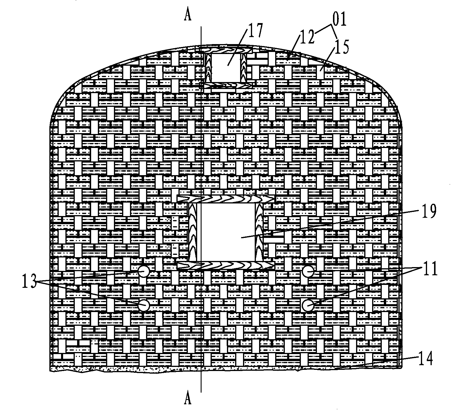
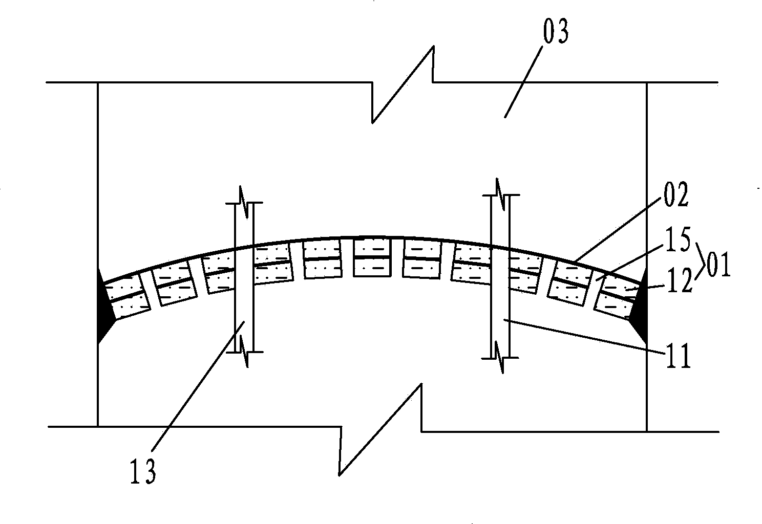
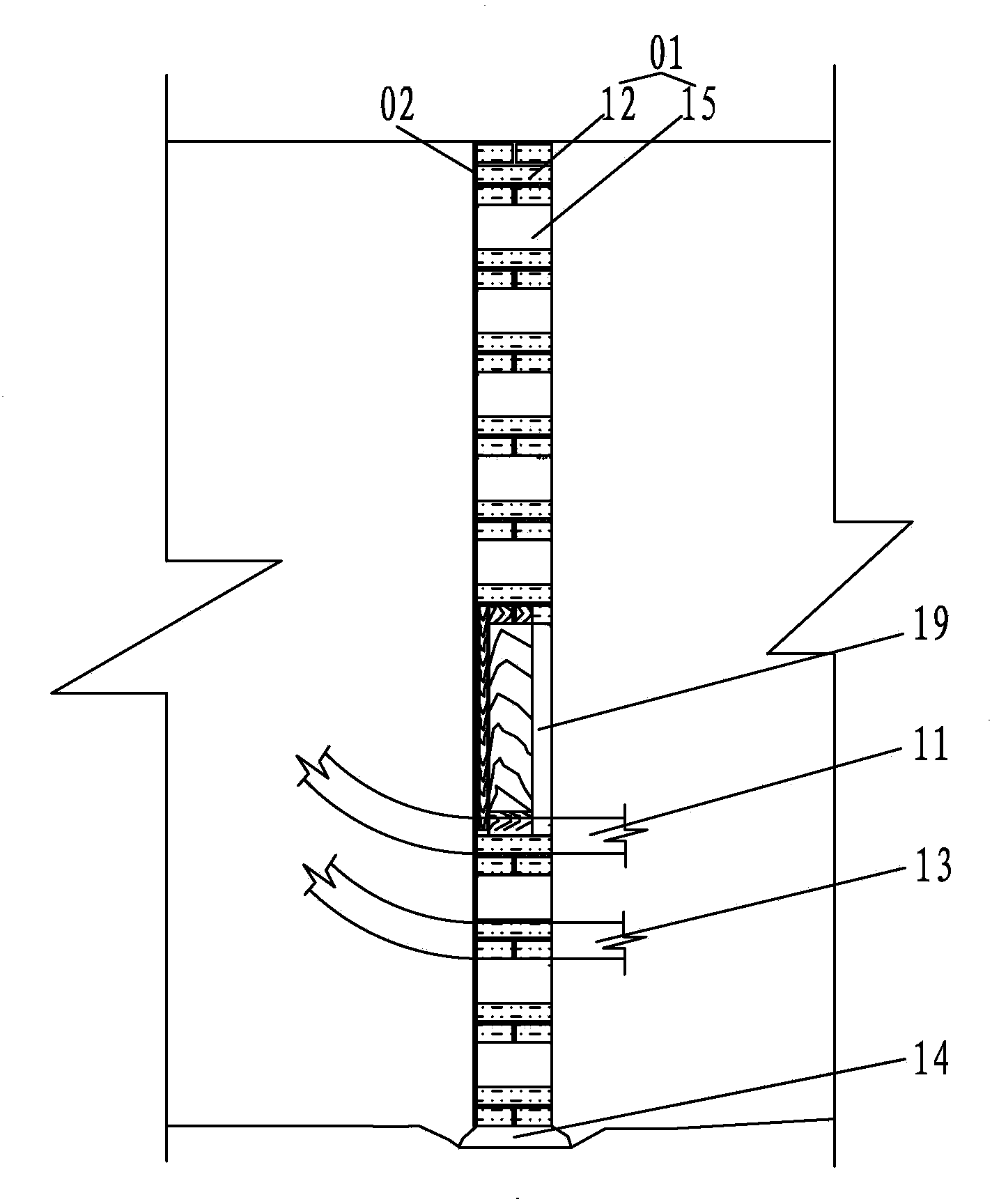
[0015] Such as figure 1 , 2 As shown, the brick structure drainage wall used in the filling mining method of the present invention includes a wall 01, a geotextile 02 arranged on the inner side of the wall 01, and a filling pipe 11, a filling return air return pipe 13, and a wall 01 are provided on the wall 01. The body 01 is made of bricks 12, and the bricks 12 are jointed by high-grade cement mortar, and there is a space between the bricks 12, which forms a weep hole 15, and the weep hole 15 is on the wall 01 Distributed in rows, every two adjacent rows of drainage holes 15 are staggered with each other, observation holes 17 are provided near the top of the wall body 01, pedestrian holes 19 are arranged in the middle of the wall body, and geotextile 02 is nailed to the wall body 01 by steel nails .

[0016] A wall base cement mortar cushion 14 is provided between the wall 01 and the roadway bottom plate, and the wall 01 and the roadway roof are smeared with high-grade ceme...


PUM


Abstract

A water drainage wall adopting a brick structure and used in a cut-and-fill stoping method comprises a wall body and geotechnical cloth arranged on the inner side of the wall body, wherein filling pipes and filling air-returning and water-returning pipes are arranged on the wall body; the wall body is built by bricks; intervals are reserved between the bricks and form water drainage holes; an observing hole is formed in the position close to the top of the wall body; and a man hole is formed in the middle of the wall body. The water drainage wall adopting the brick structure and used in the cut-and-fill stoping method is good in water drainage effect, not easy to block and low in cost, and has the firm wall body.

Description

technical field [0001] The invention relates to a drainage wall used in a filling mining method, in particular to a brick structure drainage wall. Background technique [0002] At present, most underground deposits at home and abroad are exploited by the filling mining method. During the stope filling process, in order to ensure the timely removal of excess water in the filling mortar, it is necessary to construct a drainage wall. The drainage walls currently used mainly include wooden structure drainage walls, steel The weaving drainage wall and the drainage wall formed by the concrete retaining wall + the drainage cage in the stope, among which the wooden structure drainage wall has the advantages of large effective drainage area and the stope can be filled after the construction is completed, but the cost is high, The construction quality requirements are high, and the larger the area of ​​the slab wall, the easier it is to deform, and the leakage of slurry is more seriou...

Claims


Application Information

Patent Timeline
Patent Type & Authority Applications(China)
IPC IPC(8): E21F15/04
Inventor 修国林杨竹周马云庆刘大兵王瑞星何顺斌李威
Owner SANSHANDAO GOLD MINE SHANDONG GOLD MINING LAIZHOU
Why Eureka
Try Eureka