
Continuously-running moving bed chemical-looping reaction system

A moving bed reactor and reaction system technology, which is applied in the fields of clean energy utilization and energy saving and emission reduction, can solve problems such as difficulty in oxygen carrier transportation, and achieve the effect of increasing the number of devices

Inactive Publication Date: 2013-11-13
UNIV OF SCI & TECH BEIJING
View PDF4 Cites 5 Cited by
  • Summary
  • Abstract
  • Description
  • Claims
  • Application Information

AI Technical Summary

Problems solved by technology

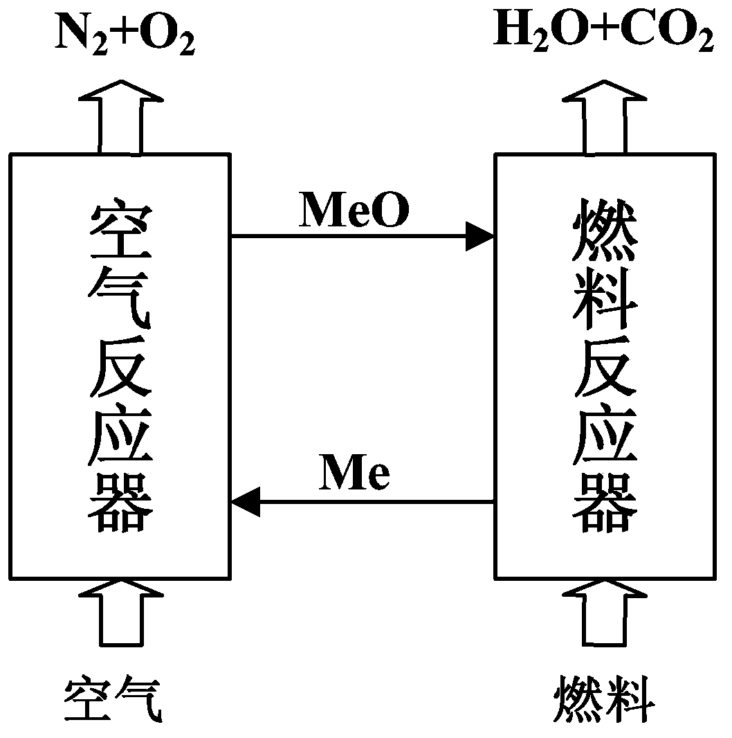
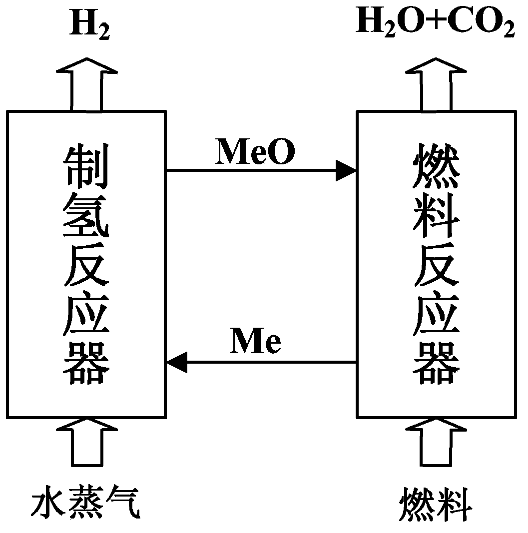
[0007] The present invention aims to solve at least one of the above-mentioned technical defects, and provides a moving bed reaction device and a circulation system capable of realizing the gaseous fuel chemical chain reaction, which can realize the dual functions of hydrogen production and heat supply without fluidizing the oxygen carrier. In this way, the energy consumption of the reactor is reduced, and the problem of difficult delivery of oxygen carriers in the serial fluidized bed chemical chain reaction system is also solved, and the structure is simple, and the manufacture, installation, operation and maintenance are convenient

Method used


Image

  • Continuously-running moving bed chemical-looping reaction system
  • Continuously-running moving bed chemical-looping reaction system
  • Continuously-running moving bed chemical-looping reaction system

Examples


Embodiment Construction

[0025] The moving bed chemical chain reaction system and its working process according to the present invention will be described below with reference to the accompanying drawings.

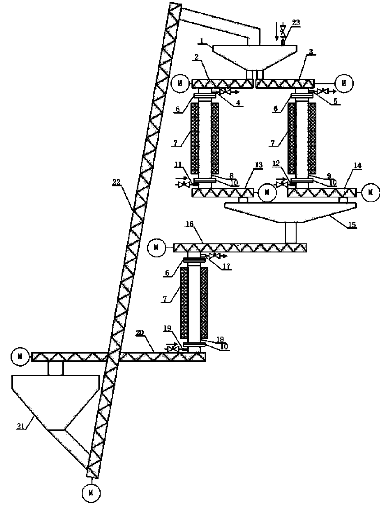
[0026] image 3 It is a schematic structural diagram of a continuously operating moving bed chemical chain reaction system according to an embodiment of the present invention.

[0027] Such as image 3 As shown, the continuously operating moving bed chemical chain reaction system includes an upper storage tank (1), a middle storage tank (15), a lower storage tank (21), and three moving bed reactors—hydrogen production reactor ( 8), the air reactor (9), the fuel reactor (18), and the screw driving mechanism, each moving bed reactor is respectively provided with the moving bed reactor inlet pipe (11, 12, 19) and the moving bed reactor row Trachea (4, 5, 17).

[0028]The screw drive mechanism includes a screw feeder (2, 3, 16) located at the top of each moving bed reactor, a screw discharger (13, ...


PUM

PropertyMeasurementUnit
diameteraaaaaaaaaa

Abstract

The invention discloses a continuously-running moving bed chemical-looping reaction system which comprises an upper storage tank, a middle storage tank, a lower storage tank, and three moving bed reactors composed of a hydrogen manufacturing reactor, an air reactor and a fuel reactor, wherein the hydrogen manufacturing reactor after being connected in parallel with the air reactor is connected in series with the fuel reactor. Fuel gas after entering the fuel reactor carries out a gas-solid reaction with an oxygen carrier so as to generate CO2 and water vapor, and after water is removed, the obtained object is compressed or sealed; and in the air reactor and the hydrogen manufacturing reactor, oxygen carrier particles respectively carry out oxidizing reaction with air and water vapor, so that the oxygen carrier particles are oxidized, and in the hydrogen manufacturing reactor, a H2 product is obtained. The moving bed reactors adopted in the system have low requirements for the size, hardness and reactive requests of oxygen carrier particles, and the oxygen carrier particles are not required to be fluidized, thereby omitting the energy consumption for fluidization conveying and fluidization and separation devices thereof; and continuous running can be realized, and the scale amplification or increase of the number of devices can be implemented according to the flow rate of gas fuels.

Description

technical field [0001] The invention relates to the technical field of clean energy utilization and energy saving and emission reduction, in particular to a continuously operating moving bed chemical chain reaction system. Background technique [0002] Under the urgent situation of global warming and energy crisis in recent years, the chemical chain cycle process can directly convert fuel into CO2 that can be stored. 2 Special attention has been paid to its unique capabilities, so countries have stepped up research and development of chemical chain technology. The chemical chain cycle process can effectively reduce CO 2 Separating energy consumption and improving the conversion efficiency of fossil energy has great commercial potential. [0003] Traditional fuel combustion or gasification processes produce CO 2 waste gas or syngas from which CO is separated 2 A series of complex post-processing processes are required. Separation of CO for current industrial applications...

Claims


Application Information

Patent Timeline
Patent Type & Authority Applications(China)
IPC IPC(8): C01B3/02C01B3/06
CPCY02E60/36
Inventor 刘训良尹晓军曹欢楼国锋苏福永豆瑞锋温治
Owner UNIV OF SCI & TECH BEIJING
Learn More