
Sectionalized dimming device of LED (light-emitting diode) lamp

A segmented dimming and LED lamp technology, which is applied to lighting devices, lamp circuit layout, light sources, etc., can solve the problem of single luminous flux function, and achieve the effects of good scalability, rich adjustment functions, and good versatility

Active Publication Date: 2015-05-27
XIAMEN YANKON ENERGETIC LIGHTING CO LTD
View PDF4 Cites 0 Cited by
  • Summary
  • Abstract
  • Description
  • Claims
  • Application Information

AI Technical Summary

Problems solved by technology

[0004] The scheme of the present invention aims at the problem of the single function of adjusting the luminous flux of LED lamps in the existing SCR mode, and proposes a solution to make the LED lamps have rich functions in the SCR adjustment mode;
[0005] The scheme of the present invention aims at the existing thyristor mode, which brings about additional adjustment line cost problem in the separation and adjustment of different loads in LED lamps, and proposes a solution, so that LED lamps can not be adjusted in more complex dimming modes. Need to add additional dimmer cost

Method used


Image

  • Sectionalized dimming device of LED (light-emitting diode) lamp
  • Sectionalized dimming device of LED (light-emitting diode) lamp
  • Sectionalized dimming device of LED (light-emitting diode) lamp

Examples


Embodiment 1

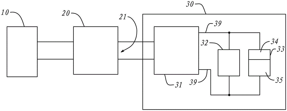
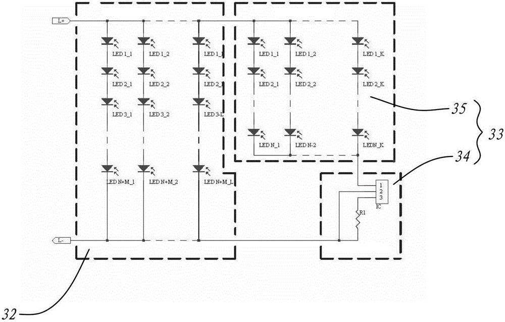
[0036] Such as Figure 1 to Figure 3 Shown is a schematic diagram of Embodiment 1 of the present invention. in, figure 1 is an overview of its overall structure, figure 2 yes figure 1 The structure and details of the main load 32 and the secondary load 33, image 3 then shows figure 1 The circuit structure of the LED driver 31.

[0037] figure 1 is a complete scheme. It includes a mains interface 10 , a thyristor dimmer 20 and a lamp 30 . The thyristor dimmer 20 is placed on an indoor wall, and its input end is connected to the live wire and neutral wire of the mains through the mains interface 10 . The thyristor dimmer 20 outputs a chopping waveform through the AC terminal 21 , and the chopping waveform changes with the adjustment of the thyristor dimmer 20 .

[0038] The lamp 30 is a whole, which includes a light source and components for controlling the light source, and has an LED driver 31 connected to the AC terminal 21 through embedded wires. The LED driver 31...

Embodiment 2

[0049] Such as Figure 4 and Figure 5 Shown is a schematic diagram of Embodiment 2 of the present invention.

[0050] This embodiment is the same as the first embodiment, and both are connected to the mains interface through a dimmer, so details are not described in the figure. Figure 4 In the lamp 30, the main load 32 is the same as that in the first embodiment, but the difference is that the secondary load includes multiple levels, including two levels of secondary loads, 33 and 43 respectively.

[0051] In particular, the secondary load of this embodiment is a cascaded multi-stage form, and the input end of the secondary load 43 is connected in parallel with the two ends of the LED light source 35 in the secondary load 33 of a previous stage to form a subsequent stage; the stage of the load Contact form such as Figure 5 The connection between the constant current module 34 of the secondary load 33 and the secondary LED light source 35 is connected to both ends of the ...


PUM


Abstract

The invention discloses a sectionalized dimming device of an LED (light-emitting diode) lamp. The sectionalized dimming device is characterized by comprising an LED driver, a primary load and a secondary load, wherein the primary load comprises a primary LED light source, and is directly connected with a driving end of the LED driver; the secondary load comprises a secondary LED light source of which the two ends are connected into a constant current module, and the input end of the secondary load is connected into the driving end of the LED driver; and voltage of the primary load is within the range of the minimum working voltage and the maximum working voltage of the secondary load. Under the control of a dimmer, states of the dimming device comprises an original state, an original regulating state and a sectionalized regulating state, wherein when the dimming device is in the original state, the primary light source of the primary load is fully bright, and the dimmer is in a maximum dimming state; when the dimming device is in the original regulating state, the dimmer is regulated, the brightness of the primary LED light source begins to change along with the dimmer, and the secondary LED light source is in a constant current normally on state; and when the dimming device is in the sectionalized regulating state, the brightness of the primary LED light source is zero, and the brightness of the secondary LED light source begins to change along with the dimmer. By adopting the scheme, the same dimmer is separated into multiple regulating sections, and each section independently corresponds to one load, so that reuse of the same dimmer is realized, and the compatibility is high.

Description

technical field [0001] The invention relates to a dimming device in the field of semiconductor lighting, in particular to a device for realizing segmental dimming of multiple light sources in an LED lamp. Background technique [0002] Dimming technology has a relatively mature scheme in the field of lighting, one of which is to use a thyristor device to chop the AC waveform, change the effective current of the light source load, and realize the change of the luminous flux. From the early incandescent light sources to the recent compact fluorescent lamps, there are more mature solutions for dimming using silicon controlled rectifiers. At this stage, with the development of LED light sources, LED light sources have already realized the replacement of traditional light sources in quite a few fields. Lamps using LED light sources are also gradually adapting to the way of thyristor dimming, and have more mature solutions . [0003] At present, LED lamps that use the thyristor d...

Claims


Application Information

Patent Timeline
Patent Type & Authority Patents(China)
IPC IPC(8): H05B37/02
Inventor 方金海余鹭帆黄学仁
Owner XIAMEN YANKON ENERGETIC LIGHTING CO LTD
Learn More