Overall structure and manufacturing method of horizontal machining center

A machining center and complete machine structure technology, applied in metal processing machinery parts, manufacturing tools, metal processing and other directions, can solve the problems of small footprint, huge volume, complicated maintenance, etc., to reduce weight, ensure transmission accuracy, reduce The effect of tooth flank wear

Active Publication Date: 2016-04-13
SHENYANG MASCH TOOL CO LTD
View PDF10 Cites 0 Cited by
  • Summary
  • Abstract
  • Description
  • Claims
  • Application Information

AI Technical Summary

Problems solved by technology

[0006] The purpose of the present invention is to provide a horizontal machining center with a small footprint and low energy consumption and a manufacturing method, which solves the problems of large volume, high energy consumption, and complicated maintenance of the existing ordinary horizontal machining centers. The structure ensures that the machine tool has a compact structure and low maintenance cost, which meets the national requirements for energy saving and emission reduction

Method used


Image

  • Overall structure and manufacturing method of horizontal machining center
  • Overall structure and manufacturing method of horizontal machining center
  • Overall structure and manufacturing method of horizontal machining center

Examples


Embodiment Construction

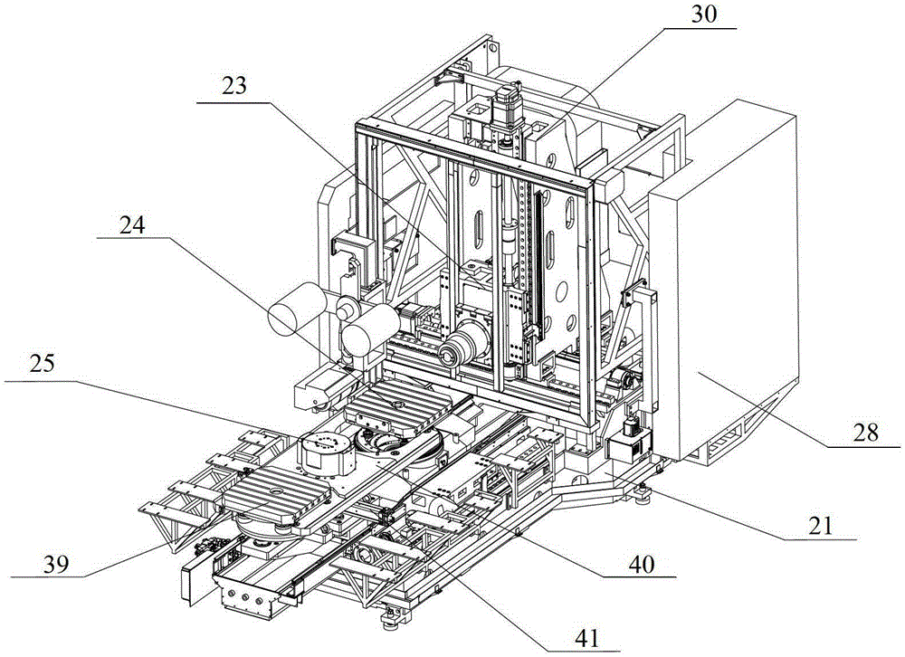
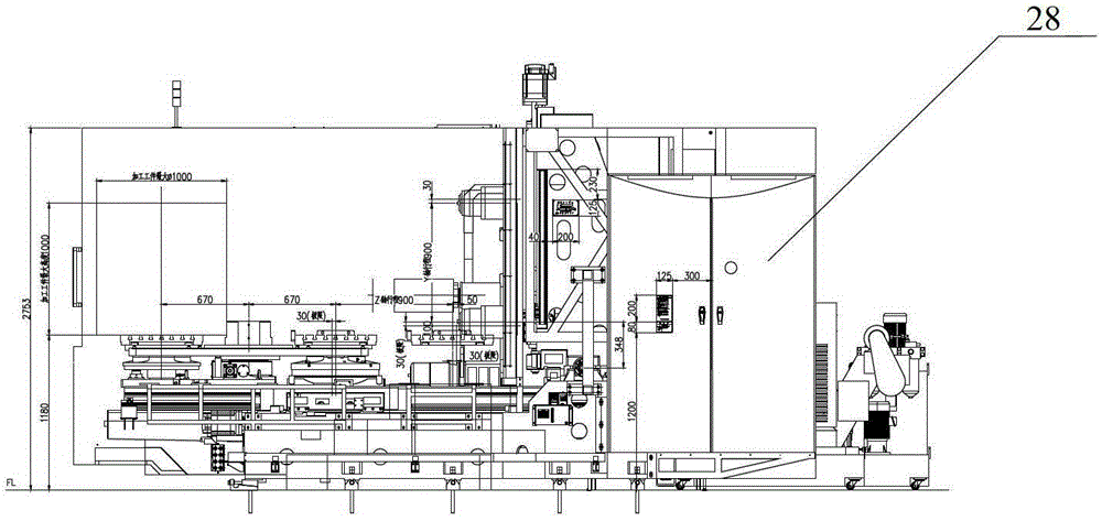
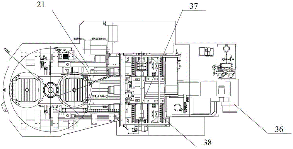
[0047] Such as Figure 1-Figure 13 As shown, the whole machine structure and manufacturing method of the horizontal machining center of the present invention, the whole machine includes a bed 21, a spindle box 23, a rotary table 24, an exchange station 25, a tool magazine 27, a column 30, etc., and the rigid bed 21 has an inclined surface Set backwater hole 32 ( Figure 12 ), the gantry frame type column 30 that moves left and right on the bed 21 adopts the rice word tendon 31 on the frame ( Figure 13 ) layout, on the spindle box 23 that moves up and down on the column 30, the motor is directly connected to the ZF reducer 1 to transmit the power to the spindle 3 through the reinforced toothed belt 2, and the loose clamping knife adopts a gas-liquid conversion booster cylinder (knife cylinder) 34 , the rotary table 24 and the three-axis transmission mechanism 33 that move forward and backward along the bed 21 adopt a modular design, the L-shaped electrical cabinet 28 with the...


PUM


Abstract

The invention relates to the field of mechanical manufacturing equipment, in particular to a complete machine structure and manufacturing method of a horizontal machining center, which belongs to the design and manufacturing technology of a numerical control machining center in a machine tool. The invention includes a bed, a column, a spindle box, a tool magazine, etc., the inclined surface of the rigid bed is provided with a water return hole, the gantry frame-type column that moves left and right on the bed has a rice-shaped rib layout, and the motor is directly connected to the spindle box that moves up and down the column. The ZF gearbox transmits the power to the main shaft through the belt, the loose clamping tool adopts the gas-hydraulic conversion pressurized cylinder, the rotary table that moves forward and backward of the bed adopts a modular design, and the frequency-variable ATC on the left side of the bed is rigid with the square tool magazine body. Connection, L-shaped electrical cabinet is used on the right side of the bed, and the combination of high-flow cutting fluid in the middle of the bed and chain plate chip conveyor has a function setting interface, maintenance planning function, and energy-saving function in terms of electrical design. The invention solves the problems of bulky volume, high energy consumption, complicated maintenance and the like of the existing common horizontal machining center.

Description

technical field [0001] The invention relates to the field of mechanical manufacturing equipment, in particular to a complete machine structure and manufacturing method of a horizontal machining center, which belongs to the design and manufacturing technology of a numerical control machining center in a machine tool. Background technique [0002] In recent years, the state has decided to revitalize the equipment manufacturing industry, focusing on supporting the vigorous development of 16 major technical equipment projects, which is also of great benefit to the development of the machine tool industry. In response to the current national requirements for energy conservation and emission reduction for enterprises, enterprises have also put forward new requirements for machine tool products. After careful market research and analysis, the current market needs machine tools that are small in size, low in energy consumption, low in maintenance costs, and meet processing requireme...

Claims


Application Information

Patent Timeline
Patent Type & Authority Patents(China)
IPC IPC(8): B23Q37/00B23Q1/26B23Q11/00B23Q3/155B23Q1/01B23Q5/36B23Q5/40
CPCY02P70/10
Inventor 易刚李永军范春宏郑永平边江王竹君孙岗存刘明科张文生王丹红王庆利朱莹陈冉李志丹王旭
Owner SHENYANG MASCH TOOL CO LTD
Why Eureka
Try Eureka