Improved lime kiln exhaust gas waste heat power generation system and power generation method thereof

An improved waste heat power generation technology, which is applied in the steam generation method using heat carrier, waste heat treatment, steam superheating, etc., can solve the problems of poor utilization of energy, large heat transfer temperature difference, insufficient power generation, etc., to achieve The effect of reducing entropy production, increasing power generation, and increasing power generation

Inactive Publication Date: 2013-10-16
广州智光节能环保有限公司
View PDF7 Cites 5 Cited by
  • Summary
  • Abstract
  • Description
  • Claims
  • Application Information

AI Technical Summary

Problems solved by technology

[0004] However, the above-mentioned lime kiln exhaust gas waste heat power generation system has the following defects: 1) The lime kiln production line attached to the general iron and steel plant has surplus saturated steam in the steam pipe network, and the steam pressure is about 1.0MPa, and the system does not utilize this surplus saturated steam , resulting in insufficient power generation; 2) Since the steam system is a single-pressure system, the heat transfer temperature difference is large, the system entropy increases, and the energy is not better utilized

Method used


Image

  • Improved lime kiln exhaust gas waste heat power generation system and power generation method thereof
  • Improved lime kiln exhaust gas waste heat power generation system and power generation method thereof
  • Improved lime kiln exhaust gas waste heat power generation system and power generation method thereof

Examples


Embodiment 1

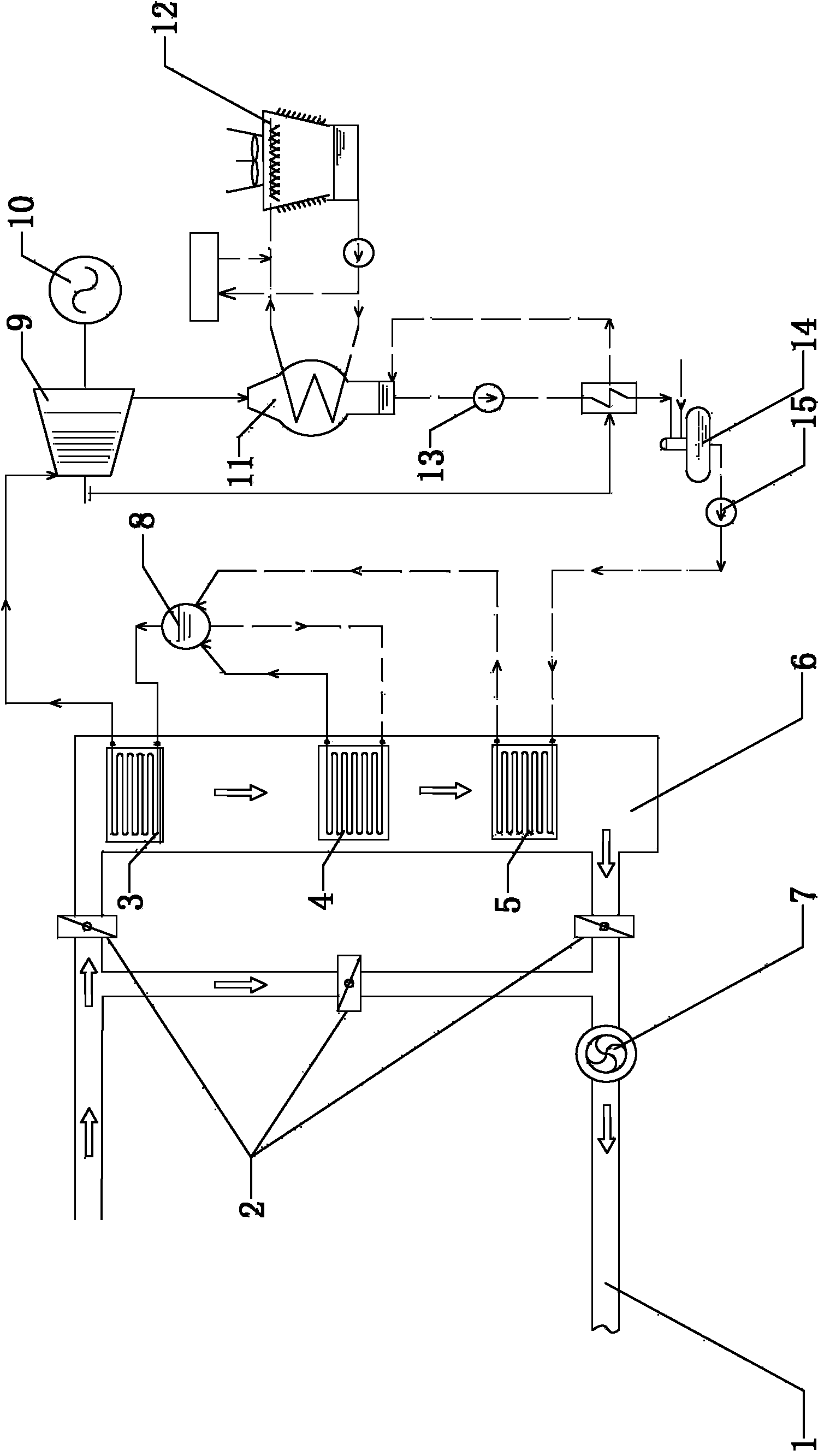
[0033] Such as figure 2 As shown, the improved lime kiln waste heat power generation system of this embodiment includes a chimney 1, a flue gas valve 2, a waste heat boiler 6, an induced draft fan 7, a steam drum 8, a steam turbine 9, a generator 10, a condenser 11, and cooling Tower 12, condensate pump 13, deaerator 14, boiler feed water pump 15, deoxygenated water return pipe 16, and surplus steam inlet pipe 17, in which superheater 3 and evaporator are arranged in order from top to bottom in said waste heat boiler 6 4 and economizer 5, the water outlet of the boiler feed water pump 15 is connected to the water inlet of the economizer 5, the water outlet of the economizer 5 is connected to the water inlet of the steam drum 8, and the evaporator 4 The water inlet is connected with the water outlet of the steam drum 8, the water outlet of the evaporator 4 is connected with the vapor-liquid two-phase inlet of the steam drum 8, and the steam inlet of the superheater 3 is connecte...

Embodiment 2

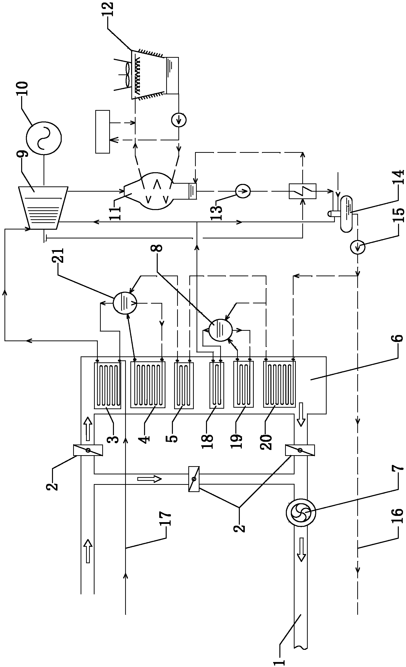
[0043] Such as image 3 As shown, the improved lime kiln waste heat power generation system of this embodiment includes a chimney 1, a flue gas valve 2, a waste heat boiler 6, an induced draft fan 7, a low pressure steam drum 8, a high pressure steam drum 21, a steam turbine 9, a generator 10, Condenser 11, cooling tower 12, condensate pump 13, deaerator 14, boiler feed water pump 15, deaeration water return pipe 16, and surplus steam inlet pipe 17, in which the waste heat boiler 6 is sequentially arranged from top to bottom High-pressure superheater 3, high-pressure evaporator 4, high-temperature economizer 5, low-pressure superheater 18, low-pressure evaporator 19, and low-temperature economizer 20, the water outlet of the boiler feedwater pump 15 and the water inlet of the low-temperature economizer 20 The water outlet of the low-temperature economizer 20 is connected to the water inlet of the high-temperature economizer 5 and the water inlet of the low-pressure steam drum 8...


PUM


Abstract

The invention discloses an improved lime kiln exhaust gas waste heat power generation system and a power generation system of the improved lime kiln exhaust gas waste heat power generation system. The power generation system comprises a chimney, exhaust gas valves, a waste heat boiler, a draught fan, a steam pocket, a steam turbine, a power generator, a condenser, a cooling tower, a condensate pump, an oxygen remover, a boiler water feeding pump, an oxygen removing water returning pipe and a redundant steam inlet pipe. A superheater, an evaporator and an economizer are sequentially arranged inside the waste heat boiler from top to bottom. The oxygen removing water returning pipe is connected with a water outlet of the boiler water feeding pump. The redundant steam inlet pipe is connected with a steam inlet of the superheater. According to the power generation method, redundant saturated steam in a steam pipe net is supplemented into the superheater inside the waste heat boiler through the redundant steam feeding pipe, the flow of superheated steam entering the steam turbine is increased, and the generated power amount is increased. According to the power generation method, a dual-pressure system can be further used, the heat transmission temperature difference is reduced, the entropy production is reduced, and the generated power amount is increased.

Description

Technical field [0001] The invention relates to a lime kiln waste heat power generation system and a power generation method thereof, in particular to an improved lime kiln waste heat power generation system and a power generation method thereof, belonging to the technical field of waste heat power generation. Background technique [0002] The existing lime kiln waste heat power generation system has a structure like figure 1 As shown, it includes the chimney 1, the flue gas valve 2, the waste heat boiler 6, the induced draft fan 7, the steam drum 8, the steam turbine 9, the generator 10, the condenser 11, and the cooling tower 12. The waste heat boiler 6 is sequentially arranged from top to bottom. There are superheater 3, evaporator 4 and economizer 5. [0003] The power generation principle of the above-mentioned lime kiln waste heat power generation system is: the inlet waste heat of the waste heat boiler 6 comes from the lime kiln preheater, the intake temperature is about 350...

Claims


Application Information

Patent Timeline
Patent Type & Authority Applications(China)
IPC IPC(8): F27D17/00F22B1/18F22G1/16F01D15/10
CPCY02P10/25
Inventor 尧志马廷全徐艳
Owner 广州智光节能环保有限公司
Why Eureka
Try Eureka