
LED lamp

A technology of LED lamps and LED light sources, which is applied in cooling/heating devices of lighting devices, lighting and heating equipment, point light sources, etc., can solve the problem that the light distribution effect and light spots cannot meet the lighting design, the cost of LED light sources increases, the current and Increased power consumption and other issues, to achieve the effects of rapid heat conduction and heat dissipation, low production cost, low power consumption and low production cost

Inactive Publication Date: 2013-10-16
朱新杰
View PDF11 Cites 1 Cited by
  • Summary
  • Abstract
  • Description
  • Claims
  • Application Information

AI Technical Summary

Problems solved by technology

However, in the actual use process, due to the increase in the power of the LED light source, the cost of the radiator, driver and LED light source increases, and at the same time, the current and power consumption increase, the heat generation is large, and the light decays quickly, which is neither energy-saving nor economical. lower cost performance
In addition, there is also a way to use a small-angle reflector in this field, but because the small-angle reflector cannot overcome the shortcomings of stray light, multiple apertures around, and uneven light, the light distribution effect and spot cannot meet the requirements of lighting design.

Method used


Image

  • LED lamp
  • LED lamp
  • LED lamp

Examples


Embodiment 1

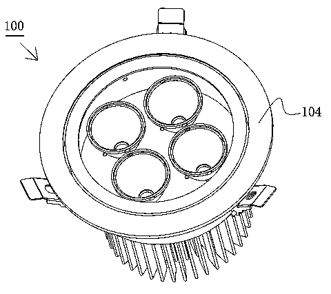
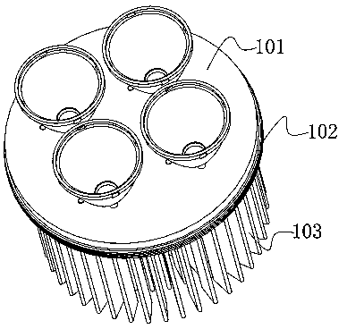
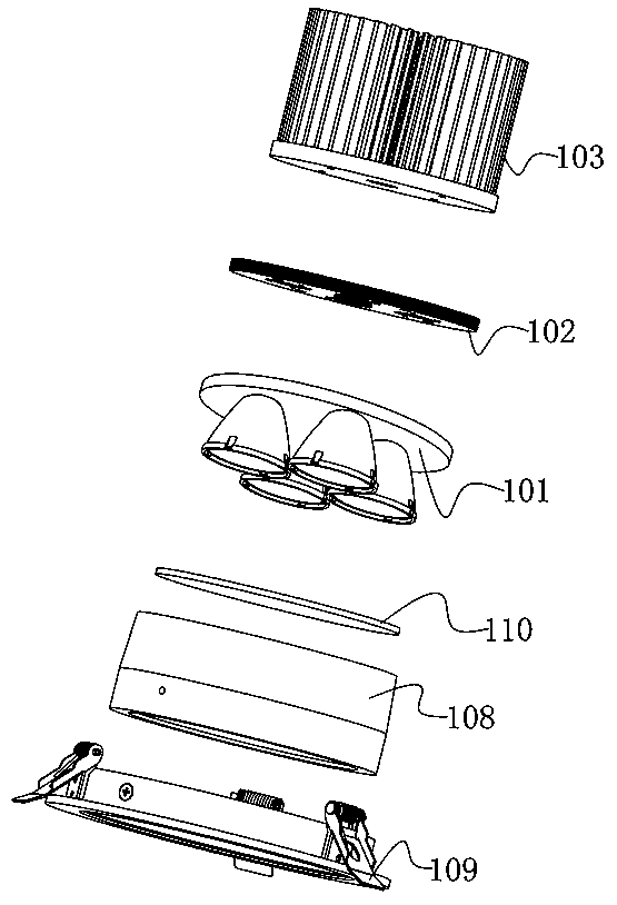
[0030] Such as Figure 1 to Figure 4 As shown, an LED lamp 100 of the present invention includes a light distribution device 101, a heat conduction plate 102, a heat sink 103 and a housing 104, the light distribution device 101 is arranged on one side of the heat conduction plate 102, and the heat sink 103 is set On the other side of the heat conducting plate 102 , the housing 104 covers the light distribution device 101 .

[0031] Such as Figure 4 As shown, the light distribution device 101 includes a substrate 105, a reflective cup 106, and an LED light source 107. At least three reflective cups 106 are arranged on the substrate 105, and an LED light source 107 is provided at one end of each reflective cup 106 facing the substrate 105. , forming a joint light distribution of multiple light sources. In this embodiment, there are four reflective cups 106 and four LED light sources 107, wherein the LED light sources 107 are COB LED light sources.

[0032] In this embodiment...

Embodiment 2

[0037] The difference between this embodiment and embodiment 1 is: as Figure 5 As shown, in this embodiment, the four reflective cups 106 are arranged in a matrix, and are integrally formed by integral injection molding. A fixed structure, such as a plate-like structure, is formed on the side of the reflective cups 106 facing away from the substrate 105. The reflective cups 106 are fixed together, which makes installation, maintenance and replacement operations easier, saves time and labor, saves labor, and reduces production costs.

[0038] Other structures are the same as in Embodiment 1.

[0039] other embodiments

[0040] In other embodiments, the number of reflector cups and LED light sources is not limited to four, but can be reduced to three, or increased to five or more, and the number and arrangement can be adjusted according to the lighting requirements of different occasions. LED light sources are not limited to COB LED light sources, and a single high-power LE...


PUM


Abstract

The invention relates to the technical field of illumination lamps, and aims to solve the technical problem that an LED lamp which is accurate in light distribution, can meet illumination requirements of different places, and is more energy-saving and low in cost at the same time is provided. The LED lamp comprises a light distribution device, a heat transfer plate, a radiator and a casing, wherein the light distribution device is arranged on one side of the heat transfer plate; the radiator is arranged on the other side of the heat transfer plate; the light distribution device is covered with the casing and comprises a substrate, reflection cups and LED light sources; at least three reflection cups are arranged on the substrate; and one LED light source is arranged at one end, facing towards the substrate, of each reflection cup, so that multi-light source combined light distribution is formed. According to the LED lamp, different beam angles and light spot effects can be obtained by adjusting the arrangement and the quantity of the reflection cups, and the illumination requirements of the different places can be met. At the same time, a plurality of the reflection cups and the LED light sources are distributed in a separated manner, so that power and heat are separated, rapid heat transfer and heat radiation can be realized, more energy is saved, and the power consumption and the production cost are lower.

Description

technical field [0001] The present invention relates to the technical field of lighting fixtures, and more specifically, to an LED lamp. Background technique [0002] In real life, LED lamps use LEDs (Light Emitting Diode) as the light source. Compared with traditional incandescent lamps and fluorescent lamps, they are energy-saving, environmentally friendly, safe and reliable, and are widely used in various fields. The current LED lamps generally include light distribution devices, heat conducting plates, radiators and other components. The light distribution devices are generally equipped with only one reflector cup, which is equipped with LED light sources, which sometimes cannot meet the requirements of high ceiling and long distance light distribution. As a result, the light is too scattered, the light concentrating effect is poor, and the light efficiency is low, which cannot meet the requirements of lighting design. [0003] In order to improve the problem of long-di...

Claims


Application Information

Patent Timeline
Patent Type & Authority Applications(China)
IPC IPC(8): F21S2/00F21V7/10F21V13/04F21V19/00F21V29/00F21Y101/02F21V29/71F21V29/77
Inventor 朱新杰
Owner 朱新杰
Learn More