Light source adjusting device
A technology for adjusting devices and light sources, which is applied in the field of optics, and can solve problems such as inability to satisfy diversification, single luminous effect, and inability to achieve different light spots.
- Summary
- Abstract
- Description
- Claims
- Application Information
AI Technical Summary
Problems solved by technology
Method used
Image
Examples
Embodiment 1
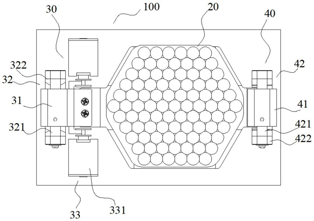
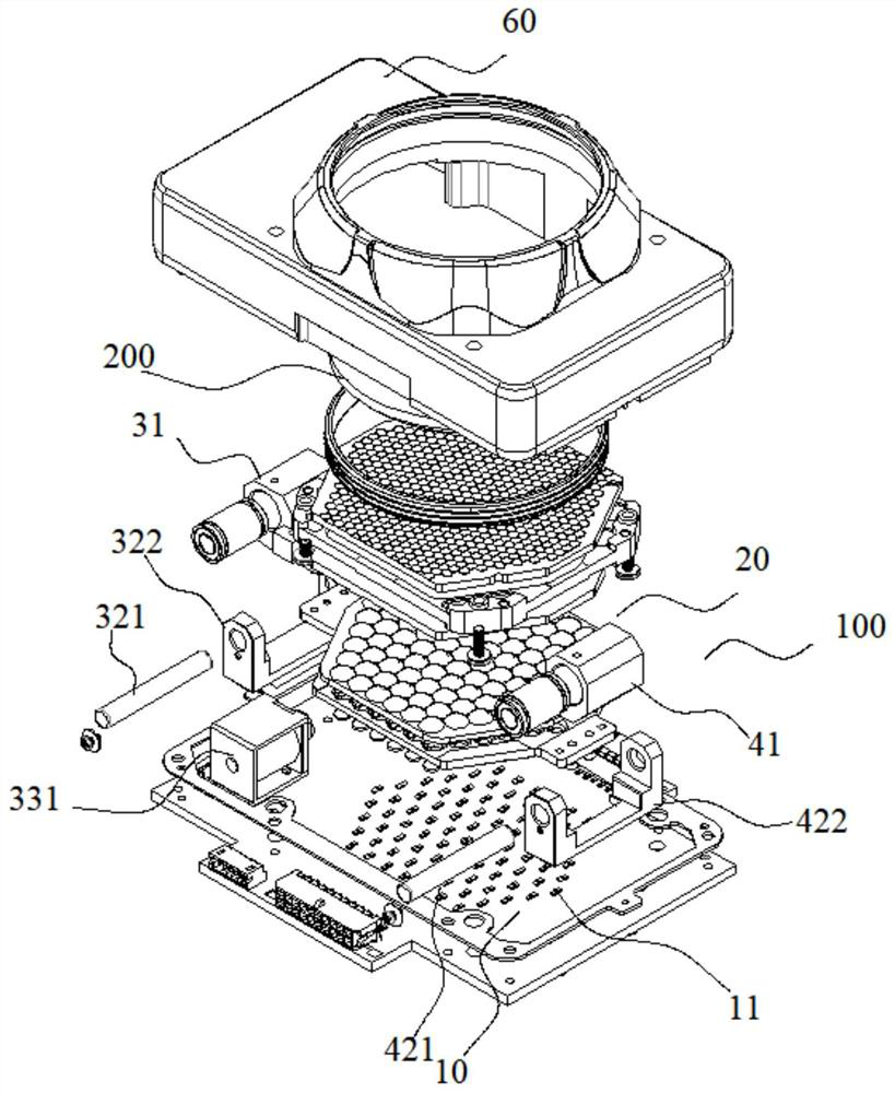
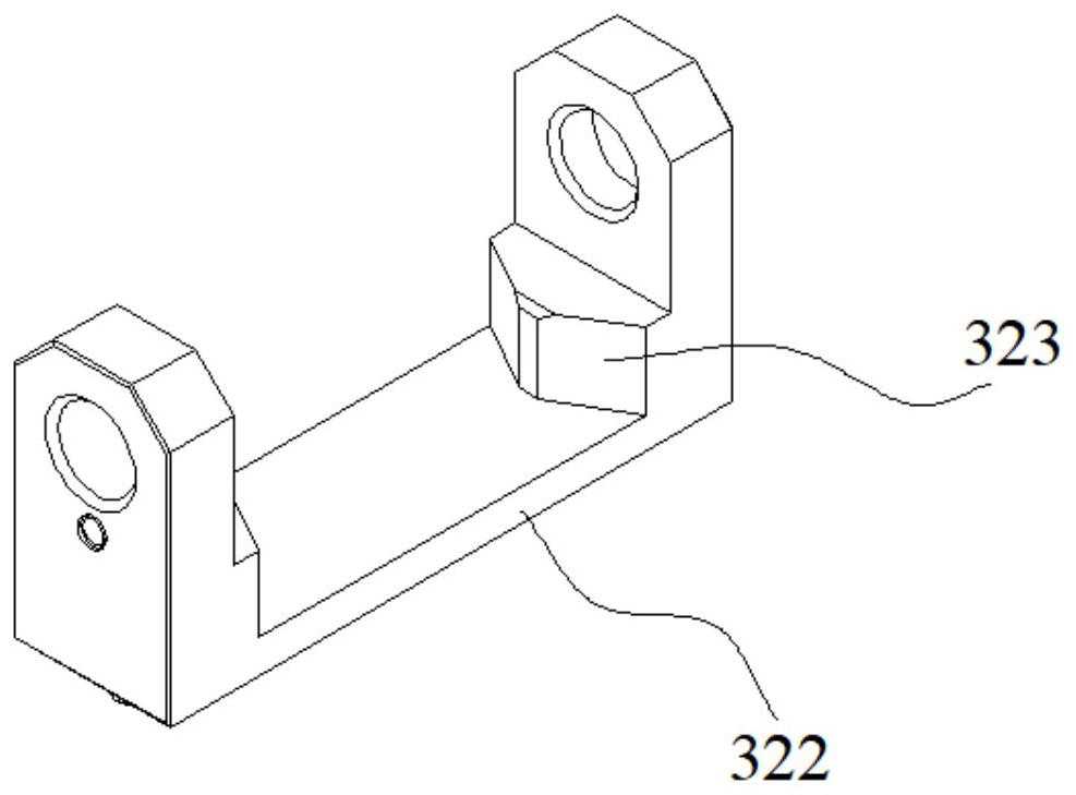
[0048] In this embodiment, each illuminant group 11 includes two different illuminants, and the position adjustment mechanism 30 is connected to the collimator lens mechanism 20 as an example. In other embodiments, more than two different illuminants may be included, and the position The adjustment mechanism 30 can be connected with the light source mechanism 10 , or the position adjustment mechanism 30 can be connected with the pinching lens mechanism 60 . When the light source adjusting device 100 of this embodiment is in the initial position, the collimating lens mechanism 20 is in the first position, and the lens unit of the collimating lens mechanism 20 is aimed at the first type of illuminant and collimates the light beam emitted by it. When the spot effect needs to be changed, the driving member 33 drives the first fixed assembly to move along the axial direction of the first shaft assembly 32, so that the collimating lens mechanism 20 is located at the second position, ...
Embodiment 2
[0074] The structure and principle of this embodiment are similar to that of Embodiment 1, the difference is that at least one group of said illuminants 11 in this embodiment includes at least three different illuminants, and said position adjustment mechanism 30 also includes a first fixed The sliding stroke of the seat assembly 31 or the second fixed seat assembly 41 is limited by the third limiting unit 50, so that the collimating lens mechanism 20 is limited to the third position or the mth position by the third limiting unit 50, so that the lens unit Aim at the third illuminant or the mth illuminant.
[0075] Such as figure 1 , figure 2 combine Figure 9 As shown, this embodiment takes limiting the sliding stroke of the second fixing seat assembly 41 as an example, and it can also be set to limit the first fixing seat assembly 31 in other embodiments. The third limiting unit 50 is a solenoid valve push rod. When the solenoid valve is energized, it can control the tele...
Embodiment 3
[0077] Such as Figure 10-11 As shown, the structure and principle of this embodiment are similar to those of Embodiment 1 and Embodiment 2. The difference is that the light source adjustment device 100 of this embodiment includes a retractable lens mechanism 60 , and the position adjustment mechanism 30 is connected to the retractable lens mechanism 60 . By setting the position adjustment mechanism 30 to connect with the retracting lens mechanism 60, the relative displacement between the retracting lens mechanism 60 and the light source mechanism 10 is controlled, so that the lens units on the retracting lens mechanism 60 can be aligned with different illuminants for retracting, thereby realizing different Spot effect.
[0078] In addition, the light source adjustment device 100 of this embodiment also includes an optical assembly 70, which is used to collimate and / or homogenize the light collected by the converging lens mechanism 60, and then output the light through the foc...
PUM
 Abstract
Description
Claims
Application Information
 - R&D
- Intellectual Property
- Life Sciences
- Materials
- Tech Scout
- Unparalleled Data Quality
- Higher Quality Content
- 60% Fewer Hallucinations
Browse by: Latest US Patents, China's latest patents, Technical Efficacy Thesaurus, Application Domain, Technology Topic, Popular Technical Reports.
© 2025 PatSnap. All rights reserved.Legal|Privacy policy|Modern Slavery Act Transparency Statement|Sitemap|About US| Contact US: help@patsnap.com


