
A compact multi-layer reflective lighting system

A multi-layer reflection and lighting system technology, applied in the field of optical lighting, can solve the problems of increasing manufacturing cost, unable to produce light spot effect, light intrusion in residential apartments, etc., and achieve the effect of miniaturization in radial size

Active Publication Date: 2018-11-27
ZHEJIANG FORESTRY UNIVERSITY
View PDF4 Cites 1 Cited by
  • Summary
  • Abstract
  • Description
  • Claims
  • Application Information

AI Technical Summary

Problems solved by technology

[0002] The traditional reflective lighting system uses a reflector. In order to collect as much light energy as possible, the size of the reflector should be as large as possible, which also increases the manufacturing cost. The unreflected light will shoot into the sky, causing light pollution, especially It is a healthy environment that causes light intrusion to nearby residential apartments and greatly affects the safety of human settlements.
There are also multi-layer reflective systems. Although they can collect light from a larger angle, the multi-layer reflectors are circular reflectors with the same size structure. This structure does not guide the light to different areas of the ground reasonably. Of course, they also produce No special flare effect

Method used


Image

  • A compact multi-layer reflective lighting system
  • A compact multi-layer reflective lighting system
  • A compact multi-layer reflective lighting system

Examples


Embodiment Construction

[0017] Specific embodiments of the present invention will be described in detail below in conjunction with specific drawings. It should be noted that the technical features or combinations of technical features described in the following embodiments should not be regarded as isolated, and they can be combined with each other to achieve better technical effects. In the drawings of the following embodiments, the same reference numerals appearing in each drawing represent the same features or components, which can be applied in different embodiments.

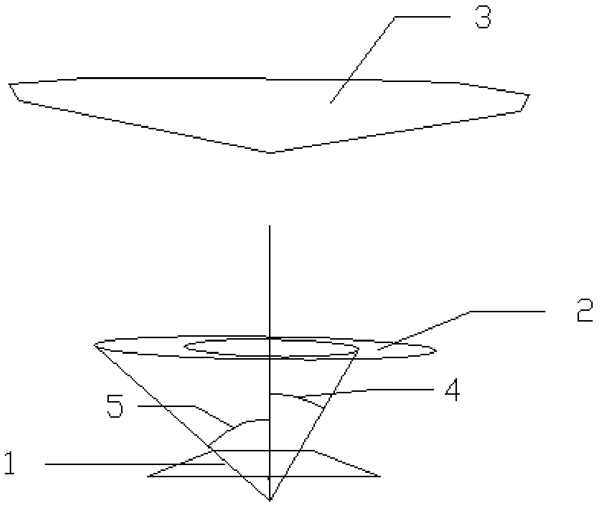
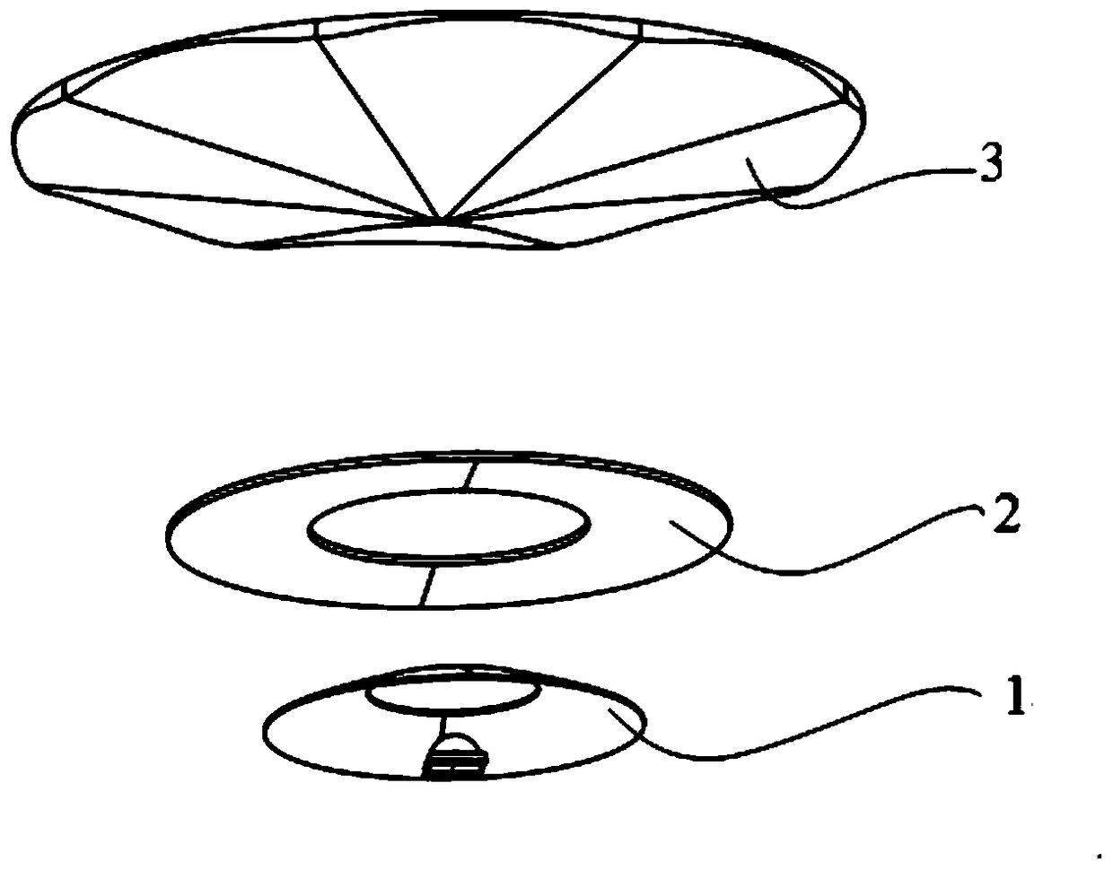
[0018] like figure 1 As shown, a compact multi-layer reflective lighting system includes a light source, a first-layer reflector 1, a middle-layer reflector 2, and a top-layer reflector 3 from bottom to top; the middle-layer reflector 2 is one or more, the first layer reflector 1 and the middle layer reflector 2 are both hollow ring structures, and the top layer reflector 3 is a circular structure;

[0019] like figure 2 As sho...


PUM


Abstract

The invention relates to the field of optical lighting and discloses a compact multilayer reflecting type lighting system which comprises a light source, a first-layer reflector, a middle-layer reflector and a top-layer reflector. The first-layer reflector and the middle-layer reflector are both of hollow annular structures, and the top-layer reflector is of a round structure; the position relationship between two layers of reflectors meets that alpha bottom is smaller than or equal beta top, the alpha bottom is an included angle between transmitted light at the inner edge of a ring of the reflector on the lower layer and the vertical direction, and the beta top is an included angle between the direction of a connecting line between the outer edge of the reflector on the upper layer and the light source and the vertical direction; and reflected light can fall out of the reflector on the lower layer after light is reflected by the top-layer reflector. According to the compact multilayer reflecting type lighting system, the reflectors of a multilayer structure are utilized to collect light energy at the maximum angle and transmit the light energy to a target area. Meanwhile, the radial sizes of the reflectors are small, and the reflectors can be conveniently integrated into lamp poles and wall lamps. The layers of reflectors respectively correspond to light at different emitting angles, and the layers of reflectors can be independently and optically designed to achieve different light spot effects in corresponding areas.

Description

technical field [0001] The invention relates to the field of optical lighting, in particular to a compact multi-layer reflective lighting system. Background technique [0002] The traditional reflective lighting system uses a reflector. In order to collect as much light energy as possible, the size of the reflector should be as large as possible, which also increases the manufacturing cost. The unreflected light will shoot into the sky, causing light pollution, especially It is a healthy environment that causes light intrusion to nearby residential apartments and greatly affects the safety of human settlements. There are also multi-layer reflective systems. Although they can collect light from a larger angle, the multi-layer reflectors are circular reflectors with the same size structure. This structure does not guide the light to different areas of the ground reasonably. Of course, they also produce There is no special spot effect. Contents of the invention [0003] The...

Claims


Application Information

Patent Timeline
Patent Type & Authority Patents(China)
IPC IPC(8): F21S8/00F21V7/00
CPCF21S8/00F21V7/0025
Inventor 戴朝卿陈瑞品
Owner ZHEJIANG FORESTRY UNIVERSITY
Learn More