Heading machine and material transfer method of heading machine
A technology for roadheaders and materials, which is applied in earthwork drilling, mining equipment, tunnels, etc. It can solve problems such as difficult miniaturization and difficult material transfer of roadheaders, and achieve the effect of improving convenience and reducing labor intensity
- Summary
- Abstract
- Description
- Claims
- Application Information
AI Technical Summary
Problems solved by technology
Method used
Image
Examples
specific Embodiment 1
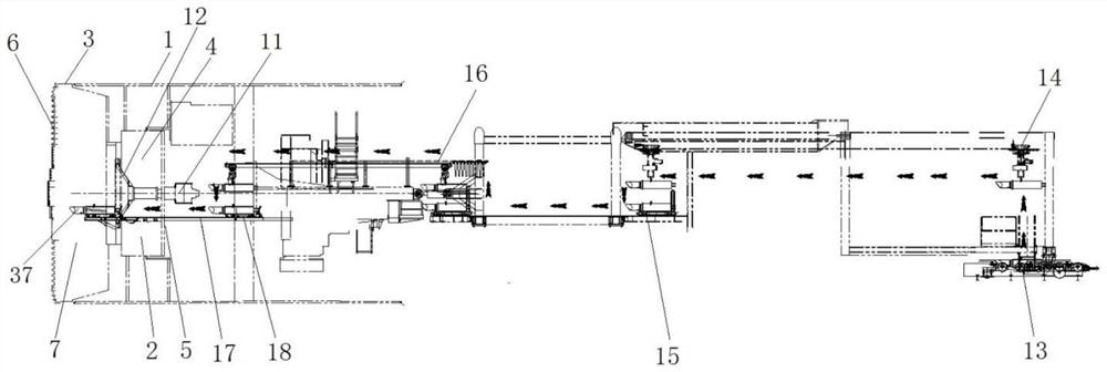
[0085] Concrete embodiment 1 of the roadheader provided by the present invention, in the present embodiment, take the roadheader as the normal pressure cutter head muddy water roadheader, the material is the knife barrel assembly 37 that cutter and knife barrel are formed, and the material transfer operation is that the material is transferred to The transfer at the cutter head is taken as an example to introduce the structure of the roadheader and the material transfer method in the present invention, as follows:
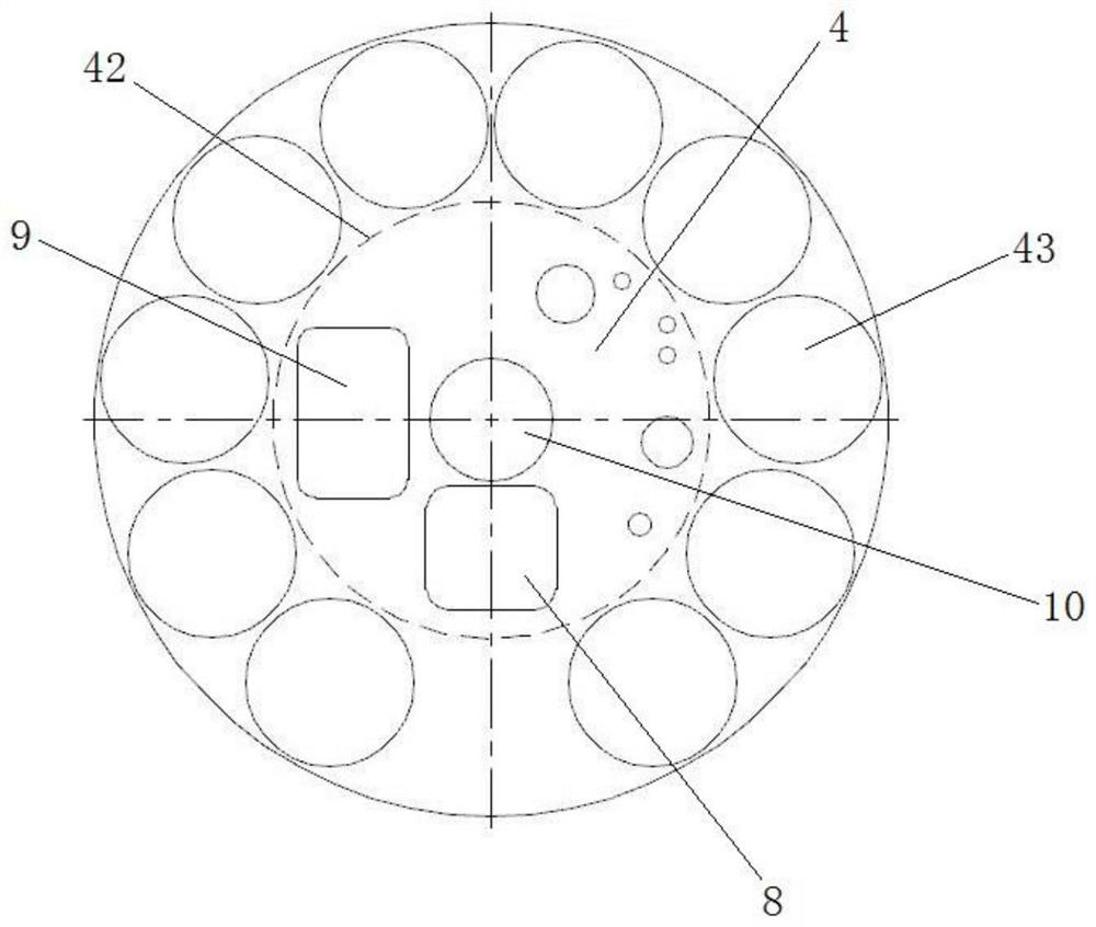
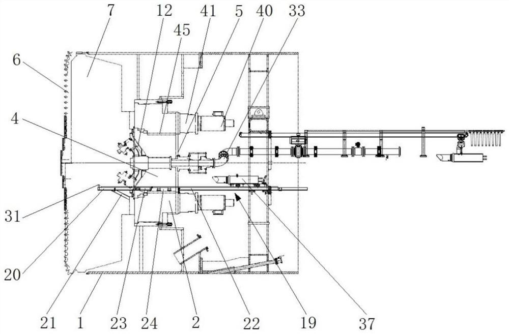
[0086] The partial structure of the boring machine provided by this embodiment is as follows: figure 1 As shown, a shield body 1 is included, and a main drive 2 is arranged in the shield body 1. The main drive 2 has a drive box, and the main drive 2 is installed with a cutter head 3 through a cutter head installation structure. In order to drive the cutter head to rotate, the main drive 2 also has a driving device, such as image 3 As shown, the driving device inc...
specific Embodiment 2
[0108] The specific embodiment 2 of the roadheader provided by the present invention mainly differs from embodiment 1 in that in embodiment 1, the crossbeam on the rear side of the cutter head is a figure-eight beam. In this embodiment, the crossbeam is any The cutter head is connected before the rotating part of the central rotary joint so that the cutter head can drive the structure of the rotating part of the central rotary joint. For example, the crossbeam can be a straight beam, and the two ends of the straight crossbeam pass along the front and rear directions. The connecting arm is connected with the cutter head, and the middle part is connected with the rotating part of the central rotary joint through the connecting arm extending along the front and rear direction.
specific Embodiment 3
[0109]The specific embodiment 3 of the roadheader provided by the present invention mainly differs from embodiment 1 in that in embodiment 1, the movement path of the material transfer trolley passes through the bottom of the main drive center cabin. In this embodiment, the material channel It is set on the side of the installation hole of the slewing center, so that the movement path of the material transfer trolley passes by the side of the central passage. For this structure, when transferring materials, the beam can be turned to a vertical state, so that the material can pass by the side of the beam. Of course, in other embodiments, the material channel can also be opened above the installation hole of the central rotary joint, so that the moving path of the material transfer trolley passes through the upper part of the central channel and carries the material through the top of the beam.
[0110] The specific embodiment 4 of the roadheader provided by the present invention...
PUM
 Abstract
Description
Claims
Application Information
 - R&D
- Intellectual Property
- Life Sciences
- Materials
- Tech Scout
- Unparalleled Data Quality
- Higher Quality Content
- 60% Fewer Hallucinations
Browse by: Latest US Patents, China's latest patents, Technical Efficacy Thesaurus, Application Domain, Technology Topic, Popular Technical Reports.
© 2025 PatSnap. All rights reserved.Legal|Privacy policy|Modern Slavery Act Transparency Statement|Sitemap|About US| Contact US: help@patsnap.com


