
Light source device

A light source device and light source technology, applied in the field of optics, can solve the problems that LED light source modules cannot achieve the presentation of different light spots, cannot meet diversified needs, and have a single luminous effect.

Inactive Publication Date: 2022-01-11
GUANGZHOU UNIONLUX ELECTRONICS TECH CO LTD
View PDF1 Cites 0 Cited by
  • Summary
  • Abstract
  • Description
  • Claims
  • Application Information

AI Technical Summary

Problems solved by technology

[0004] The present invention aims to overcome at least one defect (deficiency) of the above-mentioned prior art, and provides a light source device, which is used to solve the problem that the existing LED light source modules usually cannot realize the presentation of different light spots, and the luminous effect is relatively single, which cannot satisfy multiple needs

Method used


Image

  • Light source device
  • Light source device
  • Light source device

Examples


Embodiment Construction

[0031] The accompanying drawings of the present invention are only for illustrative purposes, and should not be construed as limiting the present invention. In order to better illustrate the following embodiments, some components in the drawings will be omitted, enlarged or reduced, and do not represent the size of the actual product; for those skilled in the art, some known structures and their descriptions in the drawings may be omitted. understandable.

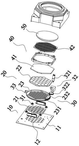
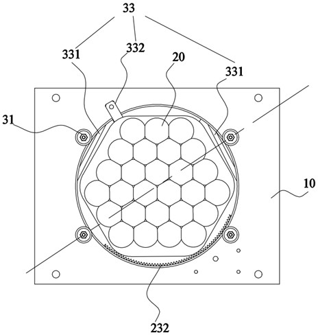
[0032] Such as Figure 1-Figure 4 A light source device shown, comprising:

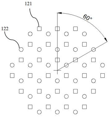
[0033] The light source mechanism 10 includes a base plate 11 and at least two different sets of illuminants 12 arranged on the base plate 11, the optical centers of each set of illuminants 12 coincide, and the sets of illuminants 12 are arranged at angles to each other;

[0034] A collimator lens mechanism 20, configured to converge and / or collimate the light beam emitted by the light source mechanism 10;

[0035] Rotate the adjustment mechanis...


PUM


Abstract

The invention relates to a light source device which comprises a light source mechanism, a collimating lens mechanism and a rotary adjusting mechanism, wherein the light source mechanism comprises at least two different light-emitting body sets, the optical centers of the light-emitting body sets coincide, and the light-emitting body sets are arranged at an angle; the collimating lens mechanism is used for collimating light beams; and the rotary adjusting mechanism comprises a driving assembly for driving a connecting assembly to rotate and a limiting assembly. According to the invention, at least two different light-emitting body sets are arranged, so that the light source mechanism emits at least two different light beams, each light-emitting body set is arranged at an angle, and the rotary adjusting mechanism is connected with the collimating lens mechanism, so that the collimating lens mechanism and the light source mechanism are controlled to rotate relatively, and the collimating lens mechanism can be aligned with different light-emitting body sets for collimation. Due to the fact that the optical centers of the light-emitting body sets coincide, and the collimating lens mechanism is driven by the driving assembly to rotate, the optical center of the whole light source mechanism does not deviate all the time.

Description

technical field [0001] The present invention relates to the field of optical technology, and more specifically, to a light source device. Background technique [0002] LED light sources are widely used in various lighting fields. Among them, LED light sources for high-power stage lights are composed of substrates, LED light-emitting units, collimation / receiving systems, uniform light systems, converging lenses, and housings. Among them, the LED light-emitting unit corresponds to the collimation / light-receiving system one by one, and the light emitted by the LED light-emitting unit is collimated and then imaged to the focal point through the converging lens. [0003] When collimating the light source structure of the stage light, the lens unit is used to align the optical center of the LED chip to achieve the optimal collimation effect; however, the spot effect presented by a single LED chip is a single effect, if different If the color temperature or spot effect of differen...

Claims


Application Information

Patent Timeline
IPC IPC(8): F21S10/00F21V5/04F21V5/00F21V14/06F21V19/00F21Y115/10
CPCF21S10/00F21V5/04F21V5/008F21V14/06F21V19/001F21Y2115/10
Inventor 不公告发明人
Owner GUANGZHOU UNIONLUX ELECTRONICS TECH CO LTD
Learn More