
Punching machine with automatic feeding function

A technology of automatic feeding and punching machine, used in metal processing equipment, feeding devices, manufacturing tools, etc., can solve the problems of low machining accuracy, imperfection, and inability to apply large metal rods, to improve production speed and processing. The effect of precision

Active Publication Date: 2013-10-16
广东澳美高新科技有限公司
View PDF5 Cites 30 Cited by
  • Summary
  • Abstract
  • Description
  • Claims
  • Application Information

AI Technical Summary

Problems solved by technology

However, the current hydraulic punching machine is not perfect in the field of continuous punching, and is limited to continuous punching of some strip-shaped metal profiles. For example, the Chinese patent application number is CN201220012280, and the name of the invention is a strip-shaped metal profile processing machine. The patent is developed for the lack of continuous punching equipment for bagged metal profiles in the prior art, but it cannot be applied to some large metal rods (such as metal profile rods, etc.), and there is no specific solution for metal profile rods at present. The special equipment developed for equidistant continuous punching requirements can only rely on manual control of feeding processing, with low processing accuracy and low production efficiency.

Method used


Image

  • Punching machine with automatic feeding function
  • Punching machine with automatic feeding function
  • Punching machine with automatic feeding function

Examples


Embodiment 1

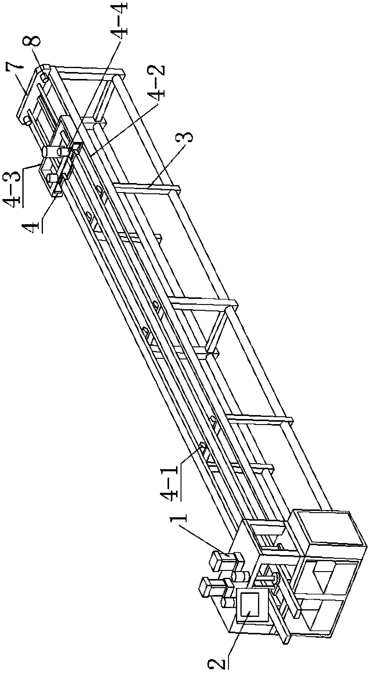
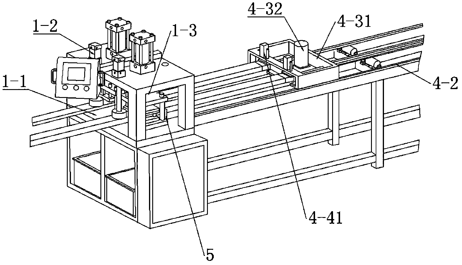
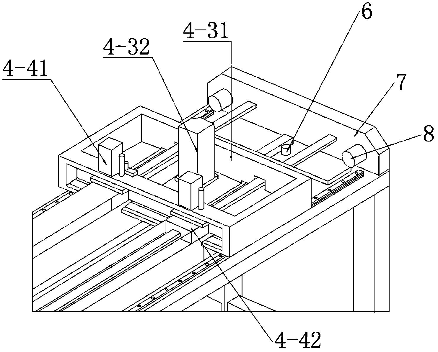
[0023] Such as Figure 1-Figure 4 As shown, an automatic feeding punching machine includes a punching mechanism 1, a control device 2, a feeding frame 3 and an automatic feeding mechanism 4 arranged on the feeding frame 3, and the automatic feeding mechanism 4 includes an automatic feeding mechanism installed on the feeding frame 3 The supporting roller 4-1 on the top, the linear guide rail 4-2, the driving mechanism 4-3 provided on the linear guide rail 4-2, the driving mechanism 4-3 is provided with a clamping mechanism 4-4, which is used to fix the profile and pass The control device drives the driving mechanism to send the profiles into the punching mechanism 1 for punching; the driving mechanism 4-3 includes a traction trolley 4-31 and a servo motor 4-32 that drives the traction trolley to move along the linear guide rail 4-2. The servo motor 4 -32 is connected with the control device 2, and the motion state of the traction trolley is controlled by the control device 2; t...

Embodiment 2

[0027] The difference between this embodiment and the above-mentioned embodiment is that the material clamping mechanism includes a material clamping seat and a clamping cylinder, the material clamping seat is composed of a bottom plate and left and right side plates, and the clamping cylinder is vertically arranged above the bottom plate, The left and right side plates can realize the positioning of the left and right sides of the profile, and the clamping cylinder is used to press the profile onto the clamping seat to realize the up and down positioning of the profile. There are at least two clamping seats and clamping cylinders, so that the automatic feeding mechanism can send two profiles to the punching mechanism at one time, and carry out the punching process on the two profiles at the same time to improve production efficiency. At least one of the left and right side panels is connected with a width adjusting mechanism for adjusting the distance between the two side pane...


PUM


Abstract

The invention discloses a punching machine with an automatic feeding function. The punching machine with the automatic feeding function is characterized in that the punching machine comprises a punching mechanism, a control device, a feeding machine frame and an automatic feeding mechanism arranged on the feeding machine frame, the automatic feeding mechanism comprises a carrying roller installed on the feeding machine frame, a linear guideway, and a traveling mechanism arranged on the linear guideway, a clamping mechanism is arranged on the traveling mechanism, the traveling mechanism comprises a trailer wagon and a servo motor driving the trailer wagon to move along the linear guideway, the servo motor is connected with the control device, the control device controls the moving state of the trailer wagon, the punching mechanism comprises a supporting platform, a pressing cylinder, an upper puncher pin, and a lower die core arranged in the inner cavity of a sectional material, a recess corresponding to the upper puncher pin is formed in the upper surface of the lower die core, a die inner core pulling rod is arranged on the feeding machine frame, the lower die core is fixed at one end of the die inner core pulling rod, and the die inner core pulling rod is parallel to the linear guideway and penetrates through the trailer wagon. The punching machine with the automatic feeding function is simple in operation, high in production efficiency, and high in product accuracy.

Description

technical field [0001] The invention relates to the technical field of punching machines, and more specifically relates to an automatic feeding punching machine. Background technique [0002] Punching machines are active parts that force metal into dies for sheet processing, stamping, molding, embossing, etc. Since the punching machine has only been developed for less than 20 years, and its development in China has only been more than ten years, there are still many imperfections, and there is no unified industry standard. At present, there are three kinds of punching machines: mechanical punching machine, pneumatic punching machine and hydraulic punching machine. Hole punching machine is a kind of pneumatic punching die that is auxiliary to bag making machine, mainly used for punching plastic bags and paper products; hydraulic punching machine is suitable for punching L, H flat steel, copper bar and aluminum bar. The focus of the present invention is the hydraulic punchin...

Claims


Application Information

Patent Timeline
IPC IPC(8): B21D43/04B21D28/24
Inventor 曾雪冰蓝宗标王卓农敬
Owner 广东澳美高新科技有限公司
Learn More